B. Intellifire Ignition System
| Symptom |
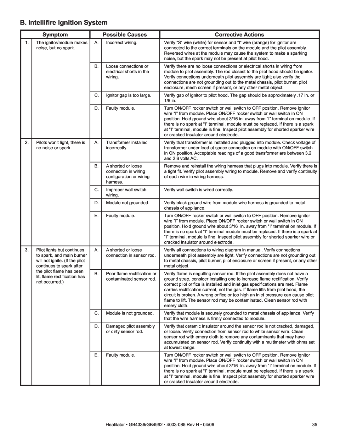
| Possible Causes | Corrective Actions |
1. | The ignitor/module makes | A. | Incorrect wiring. | Verify “S” wire (white) for sensor and “I” wire (orange) for ignitor are |
| noise, but no spark. |
|
| connected to the correct terminals on the module and the pilot assembly. |
|
|
|
| Reversed wires at the module may cause the system to make a sparking |
|
|
|
| noise, but the spark may not be present at pilot hood. |
|
| B. | Loose connections or | Verify there are no loose connections or electrical shorts in wiring from |
|
|
| electrical shorts in the | module to pilot assembly. The rod closest to the pilot hood should be ignitor. |
|
|
| wiring. | Verify connections underneath pilot assembly are tight; also verify the |
|
|
|
| connections are not grounding out to the metal chassis, pilot burner, pilot |
|
|
|
| enclosure, mesh screen if present, or any other metal object. |
|
| C. | Ignitor gap is too large. | Verify gap of ignitor to pilot hood. The gap should be approximately .17 in. or |
|
|
|
| 1/8 in. |
|
| D. | Faulty module. | Turn ON/OFF rocker switch or wall switch to OFF position. Remove ignitor |
|
|
|
| wire “I” from module. Place ON/OFF rocker switch or wall switch in ON |
|
|
|
| position. Hold ground wire about 3/16 in. away from “I” terminal on module. If |
|
|
|
| there is no spark at “I” terminal, module must be replaced. If there is a spark |
|
|
|
| at “I” terminal, module is fi ne. Inspect pilot assembly for shorted sparker wire |
|
|
|
| or cracked insulator around electrode. |
2. | Pilots won’t light, there is | A. | Transformer installed | Verify that transformer is installed and plugged into module. Check voltage of |
| no noise or spark. |
| incorrectly. | transformer under load at space connection on module with ON/OFF switch |
|
|
|
| in ON position. Acceptable readings of a good transformer are between 3.2 |
|
|
|
| and 2.8 volts AC. |
|
| B. | A shorted or loose | Remove and reinstall the wiring harness that plugs into module. Verify there is |
|
|
| connection in wiring | a tight fi t. Verify pilot assembly wiring to module. Remove and verify continuity |
|
|
| confi guration or wiring | of each wire in wiring harness. |
|
|
| harness. |
|
|
| C. | Improper wall switch | Verify wall switch is wired correctly. |
|
|
| wiring. |
|
|
| D. | Module not grounded. | Verify black ground wire from module wire harness is grounded to metal |
|
|
|
| chassis of appliance. |
|
| E. | Faulty module. | Turn ON/OFF rocker switch or wall switch to OFF position. Remove ignitor |
|
|
|
| wire “I” from module. Place ON/OFF rocker switch or wall switch in ON |
|
|
|
| position. Hold ground wire about 3/16 in. away from “I” terminal on module. If |
|
|
|
| there is no spark at “I” terminal module must be replaced. If there is a spark at |
|
|
|
| “I” terminal, module is fi ne. Inspect pilot assembly for shorted sparker wire or |
|
|
|
| cracked insulator around electrode. |
3. | Pilot lights but continues | A. | A shorted or loose | Verify all connections to wiring diagram in manual. Verify connections |
| to spark, and main burner |
| connection in sensor rod. | underneath pilot assembly are tight. Verify connections are not grounding out |
| will not ignite. (If the pilot |
|
| to metal chassis, pilot burner, pilot enclosure or screen if present, or any other |
| continues to spark after |
|
| metal object. |
| the pilot fl ame has been |
|
|
|
| B. | Poor fl ame rectifi cation or | Verify fl ame is engulfi ng sensor rod. If the pilot assembly does not have a | |
| lit, fl ame rectifi cation has | |||
|
| contaminated sensor rod. | ground strap, consider installing one to increase fl ame rectifi cation. Verify | |
| not occurred.) |
| ||
|
|
| correct pilot orifi ce is installed and inlet gas specifi cations are met. Flame | |
|
|
|
| |
|
|
|
| carries rectifi cation current, not the gas. If fl ame lifts from pilot hood, the |
|
|
|
| circuit is broken. A wrong orifi ce or too high an inlet pressure can cause pilot |
|
|
|
| fl ame to lift. The sensor rod may be contaminated. Clean sensor rod with |
|
|
|
| emery cloth. |
|
| C. | Module is not grounded. | Verify that module is securely grounded to metal chassis of appliance. Verify |
|
|
|
| that the wire harness is fi rmly connected to module. |
|
| D. | Damaged pilot assembly | Verify that ceramic insulator around the sensor rod is not cracked, damaged, |
|
|
| or dirty sensor rod. | or loose. Verify connection from sensor rod to white sensor wire. Clean |
|
|
|
| sensor rod with emery cloth to remove any contaminants that may have |
|
|
|
| accumulated on sensor rod. Verify continuity with a multimeter with ohms set |
|
|
|
| at lowest range. |
|
| E. | Faulty module. | Turn ON/OFF rocker switch or wall switch to OFF position. Remove ignitor |
|
|
|
| wire “I” from module. Place ON/OFF rocker switch or wall switch in ON |
|
|
|
| position. Hold ground wire about 3/16 in. away from “I” terminal on module. If |
|
|
|
| there is no spark at “I” terminal, module must be replaced. If there is a spark |
|
|
|
| at “I” terminal, module is fi ne. Inspect pilot assembly for shorted sparker wire |
|
|
|
| or cracked insulator around electrode. |
Heatilator • GB4336/GB4992 • | 35 |