|
| Battery |
|
| Pack |
|
| To |
WALL SWITCH | High | Junction |
| Limit | Box |
| Switch | 3V |
|
| |
|
| Adapter |
GRN* |
| BLK |
|
| BLK |
WHT | BLU | RED |
| ||
|
| BRN |
* GRN wire only used with | RED | |
| ||
optional wall switch |
|
|
|
| |
![]() Valve
Valve
Ignitor | Flame | |
Sensor | ||
| ||
Control |
| |
Box | Pilot | |
ORG |
WHT
![]() BLK
BLK
![]() ORG
ORG
![]() GRN
GRN
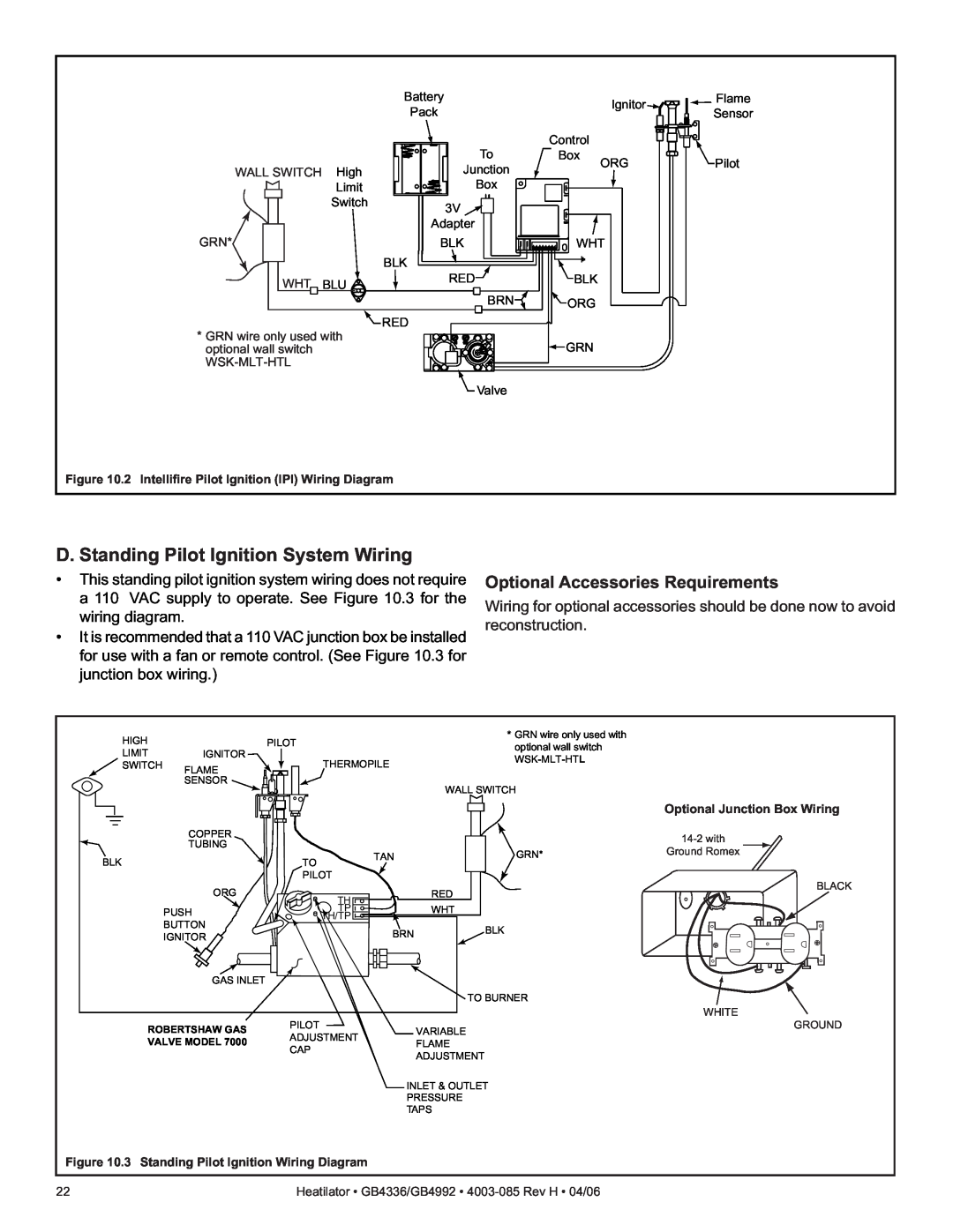
Figure 10.2 Intellifire Pilot Ignition (IPI) Wiring Diagram
D. Standing Pilot Ignition System Wiring
•This standing pilot ignition system wiring does not require a 110 VAC supply to operate. See Figure 10.3 for the wiring diagram.
•It is recommended that a 110 VAC junction box be installed for use with a fan or remote control. (See Figure 10.3 for junction box wiring.)
Optional Accessories Requirements
Wiring for optional accessories should be done now to avoid reconstruction.
HIGH |
| PILOT |
|
LIMIT | IGNITOR |
| THERMOPILE |
SWITCH | FLAME |
| |
|
|
| |
| SENSOR |
|
|
| COPPER |
|
|
| TUBING |
|
|
BLK |
| TO | TAN |
|
|
PILOT
*GRN wire only used with optional wall switch
WALL SWITCH
GRN*
Optional Junction Box Wiring
Ground Romex
ORG | TH | RED |
|
| |
PUSH | TP | WHT |
BUTTON | TH/TP |
|
| BRN | |
IGNITOR |
| |
|
| |
GAS INLET |
|
|
BLK
TO BURNER
BLACK
WHITE
ROBERTSHAW GAS | PILOT | VARIABLE | |
ADJUSTMENT | |||
VALVE MODEL 7000 | FLAME | ||
CAP | |||
| ADJUSTMENT | ||
|
| ||
|
| INLET & OUTLET | |
|
| PRESSURE | |
|
| TAPS |
GROUND
Figure 10.3 Standing Pilot Ignition Wiring Diagram
22 | Heatilator • GB4336/GB4992 • |