5K320 SATA OEM Specification
14.14Read DMA(C8h/C9h)
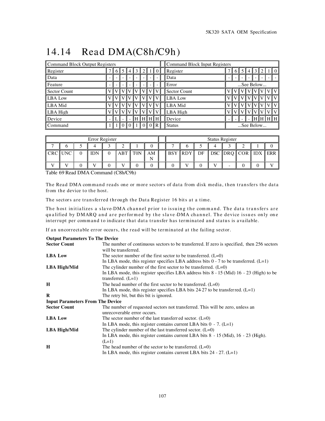
![]() Command Block Output Registers
Command Block Output Registers
Register | 7 |
| 6 | 5 |
| 4 |
| 3 | 2 |
| 1 |
| 0 |
|
Data | - |
| - | - |
| - |
| - | - |
| - |
| - |
|
Feature | - |
| - | - |
| - |
| - | - |
| - |
| - |
|
Sector Count | V |
| V | V |
| V |
| V | V |
| V |
| V |
|
LBA Low | V |
| V | V |
| V |
| V | V |
| V |
| V |
|
LBA Mid | V |
| V | V |
| V |
| V | V |
| V |
| V |
|
LBA High | V |
| V | V |
| V |
| V | V |
| V |
| V |
|
Device | - |
| L | - |
| - |
| H | H |
| H |
| H |
|
Command | 1 |
| 1 | 0 |
| 0 |
| 1 | 0 |
| 0 |
| R |
|
![]()
![]() Command Block Input Registers
Command Block Input Registers
Register | 7 |
| 6 |
|
| 5 |
| 4 |
| 3 |
| 2 |
| 1 | 0 |
Data | - |
| - |
|
| - |
| - |
| - |
| - |
| - | - |
Error |
|
|
|
| ...See Below... |
|
| ||||||||
Sector Count | V |
| V |
| V |
| V |
| V |
| V |
| V | V | |
LBA Low | V |
| V |
| V |
| V |
| V |
| V |
| V | V | |
LBA Mid | V |
| V |
| V |
| V |
| V |
| V |
| V | V | |
LBA High | V |
| V |
| V |
| V |
| V |
| V |
| V | V | |
Device | - |
| - |
|
| - |
| - |
| H |
| H |
| H | H |
Status |
|
|
|
| ...See Below... |
|
| ||||||||
Error Register
7 | 6 | 5 | 4 | 3 | 2 | 1 | 0 |
|
CRC | UNC | 0 | IDN | 0 | ABT | T0N | AM |
|
|
|
|
|
|
|
| N |
|
V | V | 0 | V | 0 | V | 0 | 0 |
|
Status Register
7 | 6 | 5 | 4 | 3 | 2 | 1 | 0 |
BSY | RDY | DF | DSC | DRQ | COR | IDX | ERR |
|
|
|
|
|
|
|
|
0 | V | 0 | V | - | 0 | 0 | V |
Table 69 Read DMA Command (C8h/C9h)
The Read DMA command reads one or more sectors of data from disk media, then transfers the data from the device to the host.
The sectors are transferred through the Data Register 16 bits at a time.
The host initializes a
If an uncorrectable error occurs, the read will be terminated at the failing sector.
Output Parameters To The Device
Sector Count | The number of continuous sectors to be transferred. If zero is specified, then 256 sectors |
| will be transferred. |
LBA Low | The sector number of the first sector to be transferred. (L=0) |
| In LBA mode, this register specifies LBA address bits 0 - 7 to be transferred. (L=1) |
LBA High/Mid | The cylinder number of the first sector to be transferred. (L=0) |
| In LBA mode, this register specifies LBA address bits 8 - 15 (Mid) 16 - 23 (High) to be |
| transferred. (L=1) |
H | The head number of the first sector to be transferred. (L=0) |
| In LBA mode, this register specifies LBA bits |
R | The retry bit, but this bit is ignored. |
Input Parameters From The Device | |
Sector Count | The number of requested sectors not transferred. This will be zero, unless an |
| unrecoverable error occurs. |
LBA Low | The sector number of the last transferr ed sector. (L=0) |
| In LBA mode, this register contains current LBA bits 0 - 7. (L=1) |
LBA High/Mid | The cylinder number of the last transferred sector. (L=0) |
| In LBA mode, this register contains current LBA bits 8 - 15 (Mid), 16 - 23 (High). |
| (L=1) |
H | The head number of the sector to be transferred. (L=0) |
| In LBA mode, this register contains current LBA bits 24 - 27. (L=1) |
107