5K320 SATA OEM Specification
14.18Read Multiple (C4h)
Command Block Output Registers |
|
|
|
|
|
|
| Command Block Input Registers |
|
|
|
|
|
|
|
|
| |||
Register | 7 | 6 | 5 | 4 | 3 | 2 | 1 | 0 |
| Register | 7 | 6 |
| 5 | 4 | 3 | 2 |
| 1 | 0 |
Data | - | - | - | - | - | - | - | - |
| Data | - | - |
| - | - | - | - |
| - | - |
Feature | - | - | - | - | - | - | - | - |
| Error |
|
| ...See Below... |
|
| |||||
Sector Count | V | V | V | V | V | V | V | V |
| Sector Count | V | V | V | V | V | V |
| V | V | |
LBA Low | V | V | V | V | V | V | V | V |
| LBA Low | V | V | V | V | V | V |
| V | V | |
LBA Mid | V | V | V | V | V | V | V | V |
| LBA Mid | V | V | V | V | V | V |
| V | V | |
LBA High | V | V | V | V | V | V | V | V |
| LBA High | V | V | V | V | V | V |
| V | V | |
Device | - | L | - | - | H | H | H | H |
| Device | - | - |
| - | - | H | H |
| H | H |
Command | 1 | 1 | 0 | 0 | 0 | 1 | 0 | 0 |
| Status |
|
|
| ...See Below... |
|
| ||||
Error Register
7 | 6 | 5 | 4 | 3 | 2 | 1 | 0 |
|
CRC | UNC | 0 | IDN | 0 | ABT | T0N | AM |
|
|
|
|
|
|
|
| N |
|
0 | V | 0 | V | 0 | V | 0 | 0 |
|
Status Register
7 | 6 | 5 | 4 | 3 | 2 | 1 | 0 |
BSY | RDY | DF | DSC | DRQ | COR | IDX | ERR |
|
|
|
|
|
|
|
|
0 | V | 0 | V | - | 0 | 0 | V |
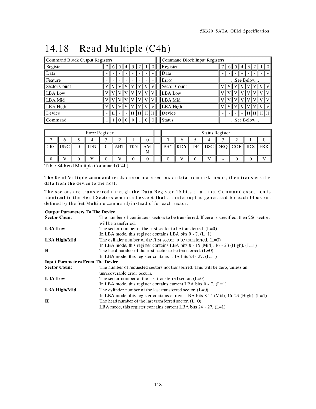
Table 84 Read Multiple Command (C4h)
The Read Multiple command reads one or more sectors of data from disk media, then transfers the data from the device to the host.
The sectors are transferred through the Data Register 16 bits at a time. Command execution is identical to the Read Sectors command except that an interrupt is generated for each block (as defined by the Set Multiple command) instead of for each sector.
Output Parameters To The Device
Sector Count | The number of continuous sectors to be transferred. If zero is specified, then 256 sectors |
| will be transferred. |
LBA Low | The sector number of the first sector to be transferred. (L=0) |
| In LBA mode, this register contains LBA bits 0 - 7. (L=1) |
LBA High/Mid | The cylinder number of the first sector to be transferred. (L=0) |
| In LBA mode, this register contains LBA bits 8 - 15 (Mid), 16 - 23 (High). (L=1) |
H | The head number of the first sector to be transferred. (L=0) |
| In LBA mode, this register contains LBA bits 24 - 27. (L=1) |
Input Paramete rs From The Device | |
Sector Count | The number of requested sectors not transferred. This will be zero, unless an |
| unrecoverable error occurs. |
LBA Low | The sector number of the last transferred sector. (L=0) |
| In LBA mode, this register contains current LBA bits 0 - 7. (L=1) |
LBA High/Mid | The cylinder number of the last transferred sector. (L=0) |
| In LBA mode, this register contains current LBA bits |
H | The head number of the last transferred sector. (L=0) |
| LBA mode, this register cont ains current LBA bits 24 - 27. (L=1) |
118