|
| 5K320 SATA OEM Specification | |
|
|
| (Hex) |
(S.M.A.R.T Function) |
|
|
|
S.M.A.R.T. Read Attribute Values | B0 |
| D0 |
S.M.A.R.T. Read Attribute Thresholds | B0 |
| D1 |
S.M.A.R.T. Enable/Disable Attribute Autosave | B0 |
| D2 |
S.M.A.R.T. Save Attribute Values | B0 |
| D3 |
S.M.A.R.T. Execute | B0 |
| D4 |
S.M.A.R.T. Read Log Sector | B0 |
| D5 |
S.M.A.R.T. Write Log Sector | B0 |
| D6 |
S.M.A.R.T. Enable Operations | B0 |
| D8 |
S.M.A.R.T. Disable Operations | B0 |
| D9 |
S.M.A.R.T. Return Status | B0 |
| DA |
S.M.A.R.T. Enable/Disable Automatic | B0 |
| DB |
(Set Features) |
|
|
|
Enable Write Cache | EF |
| 02 |
Set Transfer Mode | EF |
| 03 |
Enable Advanced Power Management feature | EF |
| 05 |
Enable | EF |
| 06 |
EF |
| 07 | |
Enable use of Serial ATA feature | EF |
| 10 |
Enable Automatic Acoustic Man agement (AAM) | EF |
| 42 |
Disable read | EF |
| 55 |
Disable reverting to power on defaults | EF |
| 66 |
Disable write cache | EF |
| 82 |
Disable Advanced Power Management feature | EF |
| 85 |
Disable Power | EF |
| 86 |
Disable use of Serial ATA feature | EF |
| 90 |
Enable read | EF |
| AA |
Disable AAM | EF |
| C2 |
Enable reverting to power on defaults | EF |
| CC |
(Set Max security extension) |
|
|
|
Set Max Set Password | F9 |
| 01 |
Set Max Lock | F9 |
| 02 |
Set Max Unlock | F9 |
| 03 |
Set Max Freeze Lock | F9 |
| 04 |
(Device Configuration Overlay) |
|
|
|
Device Configuration Restore | B1 |
| C0 |
Device Configuration Freeze Lock | B1 |
| C1 |
Device Configuration Identify | B1 |
| C2 |
Device Configuration Set | B1 |
| C3 |
|
|
|
|
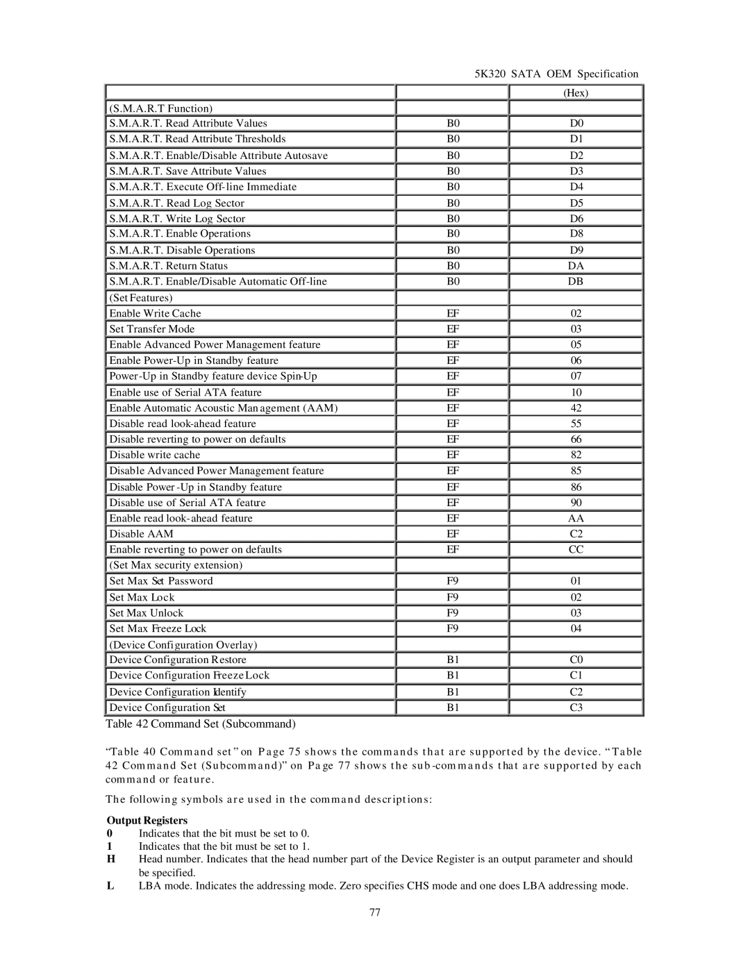
Table 42 Command Set (Subcommand)
“Table 40 Command set” on Page 75 shows the commands that are supported by the device. “ Table 42 Command Set (Subcommand)” on Page 77 shows the sub
The following symbols are used in the command descriptions:
Output Registers
0Indicates that the bit must be set to 0.
1Indicates that the bit must be set to 1.
HHead number. Indicates that the head number part of the Device Register is an output parameter and should
be specified.
LLBA mode. Indicates the addressing mode. Zero specifies CHS mode and one does LBA addressing mode.
77