CMP420V1 CMP420V2
Remarque
English
There are no user serviceable parts inside the monitor
Power Source
Prevention of Screen Burn
Public Viewing of Copyrighted Material
Features
Contents
Safety Instructions
About the Symbols
Safety Instructions
Be cautious of the power cord connection
Be sure to keep safety ground connection
Be careful in handling the battery of the remote control
Avoid a high temperature environment
Remove the power cord for complete separation
Installation environment
How to view the monitor
Precautions for the cable connection
Precaution during transportation
Do not physically impact the remote control
Set the sound volume at a suitable level
FCC Federal Communications Commission Statement Warning
Trade name Plasma Display Monitor Model Number
PW1A = 0 9,A Z or Blank
Component Names
Main Unit
Component Names Remote control
Handling the Remote Control
Loading Batteries
Installation Instructions
Installation
Anti-tumble measures
Securing to a wall or pillar
Installation Instructions
Connecting to a PC
English
Turning Power On and Off
Indicating Power status Operating
Power on
Operating Instructions
Operating Instructions Volume Adjustment
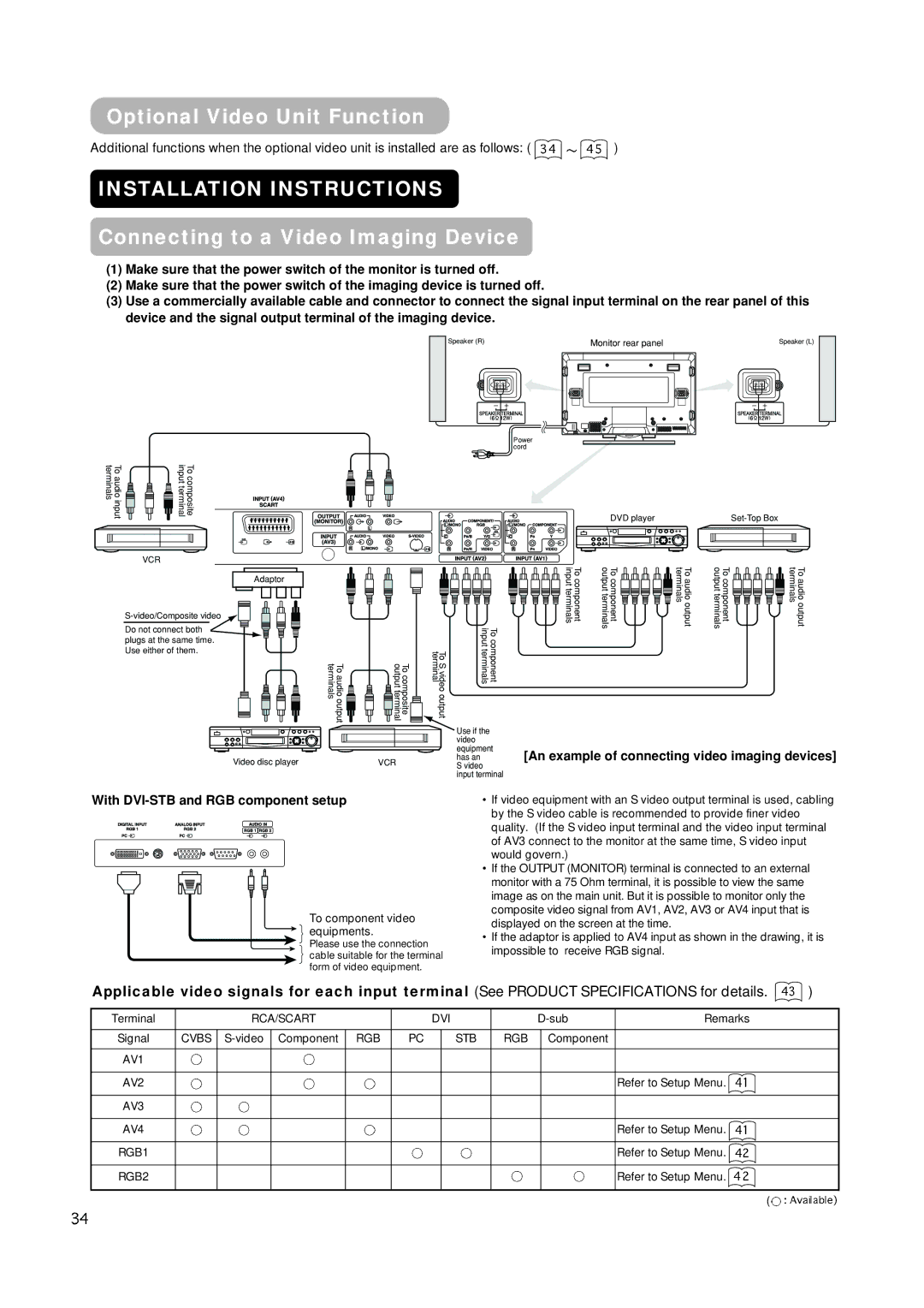
Input Switching
Audio Mute
Status guide will be displayed
Size Switching
Input Signal Screen Display
Display area selection diagram RGB input
Operating Instructions
Operating Instructions Using the Menu Screen
Automatic Adjustment of Screen Position and the Clock
On-screen display system
Independent Operation of Multiple Monitors ID No
Picture Menu
Timer Menu
Audio Menu
Function Menu
Setup Menu
Other Features
Language Menu
Automatic Store
Select a language by Select buttons and press the OK button
Other Features Signal Check
Power Save Mode
When the RGB1, RGB2 input is selected
Status Display Action
Image Retention of Plasma Display
Methods to Reduce the Occurrence of Image Retention
About screen defects
About residual images
Troubleshooting
Symptoms That Seemingly Appear to be Failures
Symptom Point to check See
Check to see if the batteries in the remote control are OK
Page
Troubleshooting Actions to Correct Abnormal Displays
Press the Select button and select Horizontal Clock
Product Specifications
Signal Input
RGB terminal D-sub 15-pin connector
Pin Input signal
Product Specifications Signal Input
Recommended Signal List
With Digital RGB signal input RGB1 input
Pin Input signal
Product Specifications Recommended Signal List
With Analog RGB signal input RGB2 input
Supplement
Connecting to a Video Imaging Device
With DVI-STB and RGB component setup
An example of connecting video imaging devices
Optional Video Unit Function
Display size selection diagram
Size button
AV1 AV2 AV3 RGB2 RGB1 AV4
Full
Using a wide-screen monitor
Press
Zoom and Cinema
Position +
Operating Instructions Displaying Multi Picture
Pictures Split
YNR
Operating Instructions Picture Menu
YNR
CNR
LTI
Color Management
Magenta
Cyan
Color Decoding
AV1
AV2 AV3
AV4
Operating Instructions Setup Menu
RGB1
Menu Display Registration condition
During VCR special playback fast forward, rewind
Output
Input connector pin specifications
Scart connector pin specifications
Pin Signal
Pin
Signal mode Horizontal Dot clock Remarks Signal Name
With R, G, B Video input AV2 and AV4 input
With component input AV1, AV2 and RGB2-component input
Vertical frequency
Page
Remarques concernant les travaux d’installation
Remarques à l’attention des revendeurs
Mises EN Garde Importantes
Prévention DES Brûlures DE Lécran
Caractéristiques
Moniteur à plasma
Grand écran d’affichage à plasma et à haute définition
Processeur numérique à haute performance
Table DES Matiéres
Remarques concernant ce Manuel
Propos des Symboles
Consignes DE Sécurité
Consignes DE Sécurité suite
Etre prudent avec le branchement du câble d’alimentation
’assurer que la mise à la terre a bien été effectuée
Faire attention lorsque l’on déplace l’écran
Ne rien placer sur l’écran
Eviter les endroits humides ou poussiéreux
Eviter un environnement où la température est élevée
Environnement d’installation
Comment regarder l’écran
Remarque concernant la rétention d’image
Comment nettoyer l’écran à plasma
Ne pas donner de chocs à la télécommande
Régler le volume sonore a un niveau adéquat
Précautions à prendre lors de l’installation
Prévention des problèmes relatifs aux récepteurs radio
NOM DES Composants
Unité Principale
NOM DES Composants suite Télécommande à distance
Utilisation de la Télécommande
Mise en Place des Piles
Instructions Concernant L’INSTALLATION
Mesures anti-basculement
Fixer à la surface de base
10 cm 4 pouces ou plus Crampon Fixation Câble Chaîne
Instructions Concernant L’INSTALLATION suite
Branchement à un Ordinateur Personnel
Branchement du Câble D’alimentation
Instructions Concernant L’OPÉRATION
Voyant indicateur
Voyant Etat Opère
’ENERGIE
Instructions Concernant L’OPÉRATION suite Réglage du Volume
Mode Sourdine Audio
Volume
Changement D’entrée
Diagramme de sélection de l’aire d’affichage Entrée RGB
Instructions Concernant L’OPÉRATION suite
Changement de la Taille
Affichage de L’écran des Signaux D’entrée
Opération Indépendante de Plusieurs Écrans N ID
Utilisation de L’écran Menu Système d’affichage à l’écran
Menu Image
Menu Audio
Menu Minuterie
Menu Fonction
Extension
Menu Réglage Initial
Menu Langue
Autres Caractéristiques
Enregistrement Automatique
Mode D’économie de L’énergie
Autres Caractéristiques suite Contrôle des Signaux
Etat Affichage Action
Lorsque l’entrée RGB1, RGB2 est choisie
Rétention DE L’IMAGE DE L’ECRAN À Plasma
Remarques
Propos de certains défauts d’écran
Propos des images résiduelles
Dépistage DES Dérangements ET CONTRE-MESURES
Symptômes Pouvant Indiquer des Dérangements
Symptômes Points à vérifier Voir
Pas d’image avec le voyant indicateur
Page
Appuyer sur le bouton Choisir Et choisir Horloge horizontale
Broche Signal d’entrée
Type de signal Sync Priorité
Caractéristiques DU Produit
Entrée des Signaux
Liste des Signaux Recommandés
Signal d’entrée
Caractéristiques DU Produit suite Entrée des Signaux suite
Terminal DVI DVI-D
Avec une entrée de signaux RGB analogique entrée RGB2
Suppléments
Fonction de L’unité Vidéo Proposée en Option
Branchement à Un Dispositif D’imagerie Vidéo
Signaux vidéo applicables pour chaque terminal d’entrée
Un exemple de branchement de
Diagramme de la sélection de la taille d’affichage
Instructions D’OPÉRATION
Changement de Taille
Presser
Utilisation avec un moniteur grand écran
Zoom et Film
Affichage de L’écran du Signal D’entrée
Deux images Séparation
Instructions D’OPÉRATION suite
Instructions D’OPÉRATION suite Menu Image suite
Contrôle des Couleurs
Jaune
Décodage des couleurs Rouge
Un item est ajouté au Menu indiqué à la
Système
Système de couleurs
Entrée vidéo
AV2 Primer paso
Entrée Audio
AV1 AV2 AV3 AV4
Sortie péritel
RGB2 Primer paso RGB2Segundo paso
Symptômes Points à vérifier
Ceci survient quelquefois lorsqu’un magnétoscope sortie
Broche Signal d’entrée
Caractéristiques DU Produit suite Entrée des Signaux
Caractéristiques de la broche du connecteur S-Entrée
Caractéristiques des broches du connecteur péritél
Avec entrée vidéo R, G, B Entrée AV2 et AV4
Avec entrée composante AV1, AV2 et RGB2 Entrée composante
PAL-N
Page
Notas sobre el Trabajo de Instalación
Nota para los Concesionarios
Hitachi
No hay piezas de servicio por el usuario dentro del monitor
Fuente DE Alimentacion
Instrucciones Importantes Para LA Seguridad
Caracteristicas
Contenido
Notas sobre este manual
Instrucciones DE Seguridad
Sobre los Símbolos
Instrucciones DE Seguridad continuación
Tenga cuidado de la conexión del cordón de alimentación
Asegúrese de mantener la conexión de tierra de seguridad
Tenga cuidado en el movimiento del monitor
No ponga ningún objeto encima del monitor
Evite un lugar húmedo o polvoriento
Evite un ambiente de alta temperatura
Ambiente de instalación
Modo de ver el monitor
Nota sobre la retención de imagen
Modo de limpiar el panel del monitor plasma
Ajuste el volumen sonoro a un nivel adecuado
Prevención de obstáculo a los receptores de radio
Precauciones en la conexión de los cables
Precauciones durante el transporte
Designacion DE LOS Componentes
Unidad Principal
Designacion DE LOS Componentes continuación Control remoto
Carga de Pilas Tratamiento del Control Remoto
Abra la tapa de pilas
Cargue las pilas
Instrucciones Para LA Instalacion
Instalación
Medidas contra caídas
Aseguramiento a una pared o poste
Instrucciones Para LA Instalacion continuación
Conexión a una PC
Conexión del Cordón de Alimentación
Instrucciones Para LA Operacion
Puesta en On y Off de la
Alimentación
Ajuste del volumen
Sordina de Audio
Conmutación de Entrada
Al presionar el botón, se visualiza la guía del estado de
Diagrama de selección del área de visualización Entrada RGB
Instrucciones Para LA Operacion continuación
Conmutación de Tamaño
Visualización de Pantalla de Señal de Entrada
Ajuste Automático de la Posición de Pantalla y del Reloj
Presione el botón OK para visualizar la pantalla de
Menu DE Imagen
Menu DE Audio
Menu DEL Temporizador
Menu DE Funcion
Items
Menu DE Configurar
Menu DE Idiomas
Otras Caracteristicas
Almacenamiento Automático
Otras Caracterristicas continuación Comprobación de Señal
Modo Ahorro de Energía
Estado Visualización Acción
Cuando se selecciona la entrada RGB1, RGB2
Retencion DE Imagen DE LA Visualizacion Plasma
Notas
Localizacion DE Fallas
Síntomas que Aparentan ser Fallas
El servicio por el cliente es peligroso
Page
Presione el botón Selecc Seleccione Configurar
La imagen aparece fluyendo figura 2 entrada RGB
De ajuste
Presione el botón Selecc
Especificaciones DEL Producto
Entrada de Señal
Terminal RGB conector D-sub de 15 clavijas
Patilla Señal de entrada
Lista de Señales Recomendadas
Con entrada de señal RGB digital entrada RGB1
Señal de entrada Patilla
Con la entrada de señal RGB análoga entrada RGB2
Suplemento
Con configuración de los componentes de DVI-STB y RGB
Función de la Unidad de Video Opcional
Conexión al Dispositivo de Imagen de Video
Un ejemplo de la conexión de los dispositivos de
Diagrama de selección del tamaño de visualización
Botón Tamaño
Cuando usted desea
Señal de entrada
Presionar
En el uso del monitor de pantalla ancha
Zoom y Cinema
Posición +
Visualización de la Pantalla de Señal de Entrada
Imágenes Divididas
Off Modo Cine PAL Filtro de Peine
Modo de Imagen
Definición
Modo Contraste
Modo Cine
Control de Colores
Amarillo
Cian
Decodificar Colores
Menu Configurar
Sistema
Sistema color
Entrada video
Entrada audio
Salida Euro
RGB2 Primer paso
RGB2 Segundo paso
El servicio realizado por el cliente mismo es peligroso
Síntoma Punto a comprobarse
La pantalla se oscurece y las imágenes no
Especificaciones DEL Producto continuación Señal de Entrada
Especificaciones de patitas conectoras de entrada S
Especificaciones de clavijas conectoras Euro
Señal
Con Entrada de Video R, G, B Entrada AV2 y AV4
Frecuencia
Observaciones
Nombre de Resolución Frecuencia vertical
Page
Page
On L5N 2L8, Canada