Dampers, Actuators and Valves
Butterfly & Flanged Control Ball Valve Ordering
How to use this guide
Fire and Smoke Resilient Seat Butterfly Valves
Dampers
Control Valve Applications
MS8105
Accessories
Section
Page
Fire and Smoke
Determine Damper Actuator Locations
Damper And Actuator Sizing
Determining Damper Actuator Torque Requirements
Approximate industry standard damper lb-in. per sq ft value
Damper Sizing
Standard Rectangular Dampers
Standard Round Dampers
Direct coupled actuators quick selection guide
Direct Coupled Actuators
Order Specification
Specification
Order Approximate
VA Rating
Lb-in 3.4 Nm
Fire & Smoke Actuators
Lb-in
Lb-in 20 Nm
Valve Selection
Page
Control Valve Applications
Way
Control Valve Selection Criteria
Stem down to close Stem up to close
Globe Control Ball Butterfly
230 psi
Port specification
AB porting
AB-B porting
Control Valve Selection Criteria
Maximum static water pressure 300 psig
Fan Coil and Zone Valves
Way
Actuator O.S. Number
Maximum Timing
Leadwire Length,
Way Way Mixing/ Diverting
Cartridge Cage Valves
For all working parts
Flush-and-fill manual lever on all actuators
Cartridge Globe Valves
Floating 02-10 Vdc
Fail Safe Pneumatic
Pipe
Way NPT Nema
Control Ball Valves ½
Vbn2dn3P0d Vbn2dn3s0d Vbn2dn3P0X Vbn2dn3s0X
Fail Safe
02-10 Vdc MA external 500 Ohm Resistor Floating
Way NPT Nema 3R
Close-off
Vbn2ab3sRa
Vbn2dn3sRd
Control Ball Valves ½- 2½
Actuator Features Non-fail Safe Fail Safe
Valve Size Inches
Control Ball Valves ½- 2½
Flanged Control Ball Valves 4
Actuator Features Non-fail Safe Fail Safe Valve Only
Way Flanged Nema 2+3R
To 5
80% of Cv on B-port
With Dedicated Valve Actuators
NPT Globe Valves ½
Valve Valve OS Close-off Pressure, psid
Number
240 psi
Ansi body class
Way water valves 15 psi Maximum steam pressure
Way steam valves, 337F 100 psi Stem travel
With Direct Coupled Actuators and Valve Linkage
Actuator Features Non-Fail Safe
Valve Valve OS
V5013N1071 V5013N1089 V5013N1097
Valve OS Close-off Pressure, psid
Spdt Built
Valve Max Static
LVaevSelection
Max Static Max Steam Flow
Flanged Globe Valves 2½
250
Psi @ 130 F Psig / 353 F Linear
125
Actuator Features
Actuator Features Fail Safe
Characteristic Action
With Tandem Direct Coupled Actuators and Valve Linkage
Threaded and Flanged Globe Valves 2
Body material Bronze V5011/13N, Cast iron
Cast Iron VGF3
Q5022A1001 Required
100 125
V5013B1003
175
Diverting
Actuator O.S. Number Power Supply
LVaevSelection
Standard Psi @ 130 F Equal %
Flanged Globe Valves 4
Close-off Pressure, psid
Standard
Max Static Max Steam
Flow Valve Valve OS Close-off Pressure, psid
Flanged Cage Valves 2½
Flow characteristic Modified linear
Action
With Pneumatic Actuators
Chart H
Rolling diaphragm for long life Low hysteresis
To the valve
Chart C
Chart a
Chart B
Chart G
10psi span
Close-off Pressure See Charts On
With Positive Positioner
Inch Direct Acting Pneumatic Actuator
Chart H Chart J Chart K
Max Steam Flow Valve
Steam
Constant Total Stem up closes B-AB V5013C1019
Chart S
Stem
PSI kPa
Way Water & Steam Valves Way Water Valves
See Charts On
Close-off Pressure
Chart W
Chart
Chart T
Way Electrically-Actuated Control
Resilient Seat Butterfly Valves
Open Normally
Field
Built Add-On
Way Normally Closed Field-Configurable Normally Open
Lever
Valve
Porting
Common
Use a pair
Valve O.S. Number
Diverting
VFF6 A-AB-B porting, full-cut
VFF6 may be piped for mixing
Control with water exiting port AB
Resilient Seat Butterfly Valves
Way Pneumatically-Actuated Control
Psi Actuator
Open
Spring Positioner Standard
Psi spring return
Cv @
Mixing
Port
1081 3316 567 1850
Page
Pneumatic Damper Actuator MP909D MP909E, H MP913 MP918A, B
Temperature Rating
Rectangular Volume Control Dampers
D1 Series
Performance Data D1 Pressure and Velocity Limits
Performance Data D2, D3 Pressure and Velocity Limits
D2 and D3 Series
D690
Round Volume Control Dampers
Type of Blade
DM7600
S03 Series MS4103 MS7403 MS7503 MS8103
Spring Return Direct Coupled Actuator
Rated Torque
S05 Series MS4105 MS7105 MS7405 MS7505 MS8105
S10 Series MS4110 MS7510 MS8110
S20 Series MS4120 MS7520 MS8120
NEMA1
ML4125 ML8125
ML4135 ML8135
ML6161 ML7161
Non-Spring Return Direct Coupled Actuator
ML6174 ML7174
N05 Series MN6105 MN7505
N10 Series MN6110 MN7510
NEMA2 IP54
N20 Series MN6120 MN7220
N34 Series MN6134 MN7234
ML4115 ML8115
Fire And Smoke Actuator
Supply Voltage
Materials
Integral junction box with three
MS4209F MS4309F MS4709F MS4809F MS8209F MS8309F
MS4120F MS4620F MS8120F
Pneumatic Damper Actuator
Temperature Range
MP909D
DIA 13 5-11/16 145 1-3/16
Actuator with Fixed External Mounting Bracket
MP909E,H
Actuator with Internal N.C. Trunnion Mounting Bracket
Actuator with External Trunnion Mounting Bracket
MP913
Actuator with Internal N.O. Trunnion Mounting Bracket
MP918A,B
100
101
MP920
MP953C,D
Pneumatic Valve Actuator
102
103
MP953E,F
104
MP958
4 DIA
IN. MM In. NPT
M4185 M8185
Modutrol IV Motor
105
Shaft Shape
106
M6184 M6194
M6285 for slaving applications
108
M6284 M6294 for slaving applications
109
M6274 M6284 M6285 M6294 Motors with Linear 10K Feedback
110
M7164
111
M7274 M7284 M7285 M7286 M7294
112
M9164 M9174 M9182 M9184 M9194
113
M9175 M9185 M9186
Q7130 Q7230 Q7330
VU443, VU444 VU843 VU844
Unitary Valve Actuator
115
11/16
VC Series Two-position Actuators
117
VC Series Proportional Actuators
VC Series Fail Safe Proportional Actuators
Visual position indication red pin
M6410 M7410
119
Visual position indication red disk
M6435 M7435
120
ML6420 ML7420
Direct Coupled Valve Actuator
121
122
ML6421 ML7421
ML6425 ML7425
Stem down on power failure or
123
ML6984
125
ML7984
VU52 VU53
Unitary Valve
126
Valve Type
127
VU54
Stem Travel
Vcza Vczb
129
Vczm Vczn
130
V5852
131
V5853
132
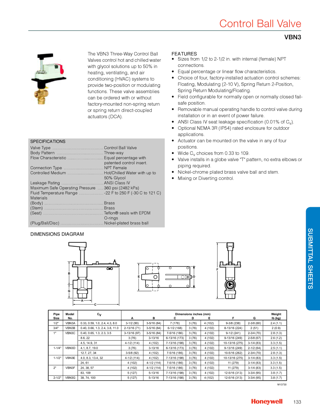
Control Ball Valve
133
VBN3
134
VBF2
135
VBF3
V5011F,G
NPT Globe Valve
136
137
V5011N
138
V5013N
V5051A
Flanged Cage Valve
139
V5011A,B
Flanged Globe Valve
140
141
V5013B,C
Actuators with Q5020 valve
MN/MS Series Direct Coupled
Linkage
142
143
VGF2 Pressure Balanced
Valve Action
144
VGF3
145
VFF1
146
VFF2
147
VFF3
148
VFF6
Q605
Damper Linkage
149
Q5001
Valve Linkage
150
Q5020
Globe Valve Linkage
151
Q5022
153
Wiring for line-voltage two-position control
Actuator Wiring Diagrams
Wiring for 02-10 VDC proportioning controllers
Wiring for Spdt on/off Control
Direct Coupled Actuators Spring Return Models
Wiring for 3 position Economizer controllers
Override to full close
155
Wiring for Floating Control Floating mode setting
Wiring for On/Off Control
156
Override to full closed Modulating mode setting
Override to full open Modulating mode setting
Terminal Block Details
157
Typical 120 Vac Wiring
Typical 24 Vac wiring Typical 230 Vac Wiring
158
ML7161 used with 4-20 mA control
ML6174 and ML7174
ML7174 used with 4-20 mA control
159
Wiring for Auxiliary Switches
Wiring for Floating Control Wiring for Voltage Control
160
MN6105, MN6110
Wiring for Modulating Control
Used for On/Off Control Wiring for Floating Control
161
Wiring for 120V Control
Wiring for 24V Control
MS4120F, MS4620F, and MS8120F
162
Foot Mounted Motors
M4185 and M8185
M6184 and M6194
M6284, M6285, and M6294 for slaving applications
Typical wiring for M7685 motors
Typical wiring for Series 70 motors
M7164, M7284, M7285, M7286, and M7294
M7685
Wiring for Potentiometer Control
Typical wiring for Series 90 motors
165
Actuators with Butterfly Valves VFF2, VFF3, and VFF6
Typical Non-Spring Return 120 Vac Floating control wiring
166
Typical Spring Return 2-Position, 24 Vac wiring
Typical Non-Spring Return Modulating control wiring
Actuators with Butterfly Valves
167
168
169
Threaded Globe Valves
Guide Specifications
170
171
Pressure-Balanced Flanged Globe Valves
172
Flanged Globe Valves
173
Threaded Control Ball Valves and Actuators
174
Control Ball Valves and Actuators
175
Flanged Butterfly Valves and Actuators
176
Fan Coil Zone Valves and Dedicated Actuators
177
Cartridge Cage Valves and Dedicated Actuators
178
Cartridge Globe Valves and Dedicated Actuators
179
Electric Large Linear Globe Valve Actuators
180
Direct-Coupled Electronic Globe Valve Actuators
181
Direct-Coupled Rotary Actuator Globe Valve Linkage
182
Tandem Direct-Coupled Rotary Actuator Globe Valve Linkage
183
Footmount Globe Valve Actuators
184
185
Ball Joints, Push Rod Accessories
Damper And Actuator Accessories
Control, Positioning, Feedback Accessories
32003532-005
Mounting Accessories
32006306-001
205649
Rotational Limiters, Position Indicators
Crankarms
Shaft Adaptor Accessories
Miscellaneous Accessories
Enclosure Accessories
Q7002 Interface Modules
Accessories for Obsolete Actuators
Valve Actuator Accessories
Valve Accessories
VU Series Fan Coil Actuator Accessories
Pneumatic Damper Actuator Parts and Accessories
Pneumatic Damper Accessories
14004264-002
14004264-001
14004324-001
14004350-001
314503
314440A
315321
315321G
Pneumatic Valve Actuator Parts and Accessories
Pneumatic Valve Accessories
311852
311851/0062
311855
311863
Foot Mounted Motor Accessories
Foot Mounted Motor Accessories
203709D2
220738A
4074ERU
221508A2
7617DM
ES-650-117
Damper and Valve Linkage Accessories
Damper And Valve Accessories
Way Valve + Non-Spring Return Modulating Actuator
Way Valve + Non-Spring Return Floating Actuator
Way Valve + Spring Return, 2-Position Actuator
Way Valve + Spring Return Floating Actuator
Direct Coupled Actuator
Competitive Cross Reference
202
203
204
Sec Actuator Lb-in Signala
±20% 25-85
205
206
Switches Sec Actuator Lb-in Signala Power
Johnson Torque Control Timing Honeywell
207
Switches Sec Actuator Lb-in Signala
208
209
210
211
212
Lb-in Signala
Invensys Torque Control Timing Honeywell
213
1kOhm
214
Lb-in Signala Power
Switches
215
Siemens Torque Control Timing Honeywell
34 Nm Floating
216
+ SW2 34 Nm Floating
+ SW2 34 Nm
217
200976C
218
219
Way Valve
Control Ball Valve Cross Reference
220
221
Way Valve + Non-Spring Return Floating Actuator
222
Way Valve + Non-Spring Return Modulating Actuator
223
Way Valve + Spring Return, 2-Position Actuator
224
Way Valve + Spring Return Floating Actuator
225
Way Valve + Spring Return Modulating Actuator
226
Globe Valve Cross Reference
227
228
Pneumatics Cross Reference
229
230
231
Modutrol IV Motor Cross Reference
232
233
234
235
236
237
238
239
240
241
242
243
Introduction
Appendix a Valve Selection and Sizing
Definitions
0000240 C
Within the temperature range
865 C
Pascals
Ansi
Butterfly Valve
Ball Valve
Iron or Steel Component Corrosive Substance Corrosion Color
Valve Material and Media
249
Valve Selection
250
Two-Way Valve Application
Linear vs. Nonlinear System Control
Flow vs. Stem Travel Characteristic of a Quick Opening Valve
252
30% open Gpm 10% increase 40% open 60% increase 50% open
Mixing valve application has a maximum pressure
Valve Sizing
253
Pressure Drop Correction for Propylene Glycol Solutions
Pressure Drop Correction for Ethylene Glycol Solutions
Conditions of temperature
= the specific volume of air at standard
For hot water coil valves
Where
256
Substituting
257
Effect of Pressure Drop in Hot Water Valve Sizing
Pressure drop in psi
Scaling constant
Superheat in degrees F
For sizing steam coil valves
At Room Termperature At 65 F Inlet Air Temperature
When sizing steam jet humidifier valves
Simplifying
Fices use
Negative value if a vacuum return
Pressure
Psig
Pressure in return is atmospheric
In. Hg = 0.49 psi and 1 psi = 2.04 in. Hg
= 80% x Pm Pr
261
Properties of Saturated Steam Boiling Point or
Volume For valve
Maximum
Specific Allowable Inches
263
Appendix B Nema Standard Classification Code for Enclosures
Shielded Wiring
265
266
Warranty Policy
Automation and Control Solutions