HP E1433A User's Guide
Module Description
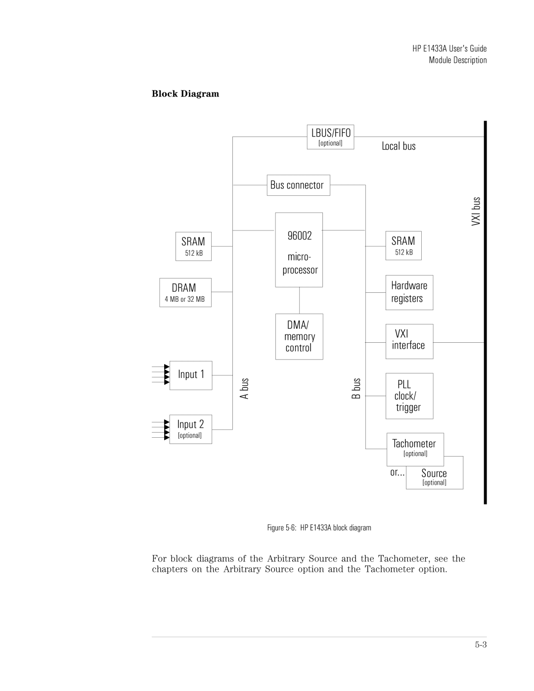
Block Diagram
SRAM
512 kB
DRAM
4 MB or 32 MB
Input 1
Input 2
[optional]
LBUS/FIFO
[optional]
![]() Bus connector
Bus connector
96002
micro- processor
DMA/ memory control
Abus | Bbus |
Local bus
VXI bus
SRAM
512 kB
Hardware registers
VXI interface
PLL clock/ trigger
Tachometer
[optional]
|
|
|
|
or... | Source | ||
| [optional] | ||
|
|
|
|
Figure 5-6: HP E1433A block diagram
For block diagrams of the Arbitrary Source and the Tachometer, see the chapters on the Arbitrary Source option and the Tachometer option.