c.Fan (see Fan on page 77)
d.Keyboard (see Keyboard on page 62)
e.Base enclosure (see Base enclosure on page 71) Remove the heat sink:
![]()
![]()
![]()
![]() NOTE: Step 2 applies to computer models equipped with a graphics subsystem with discrete memory. See step 3 for heat sink removal information for computer models equipped with a graphics subsystem with UMA memory.
NOTE: Step 2 applies to computer models equipped with a graphics subsystem with discrete memory. See step 3 for heat sink removal information for computer models equipped with a graphics subsystem with UMA memory.
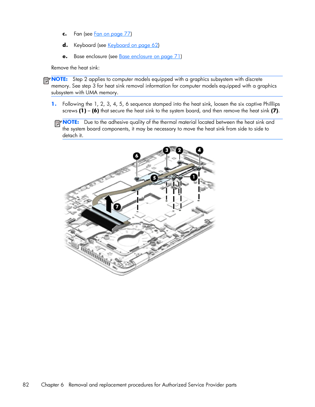
1.Following the 1, 2, 3, 4, 5, 6 sequence stamped into the heat sink, loosen the six captive Philllips screws (1) – (6) that secure the heat sink to the system board, and then remove the heat sink (7).
![]()
![]()
![]()
![]() NOTE: Due to the adhesive quality of the thermal material located between the heat sink and the system board components, it may be necessary to move the heat sink from side to side to detach it.
NOTE: Due to the adhesive quality of the thermal material located between the heat sink and the system board components, it may be necessary to move the heat sink from side to side to detach it.
82 | Chapter 6 Removal and replacement procedures for Authorized Service Provider parts |