Example: Scanning with External Device
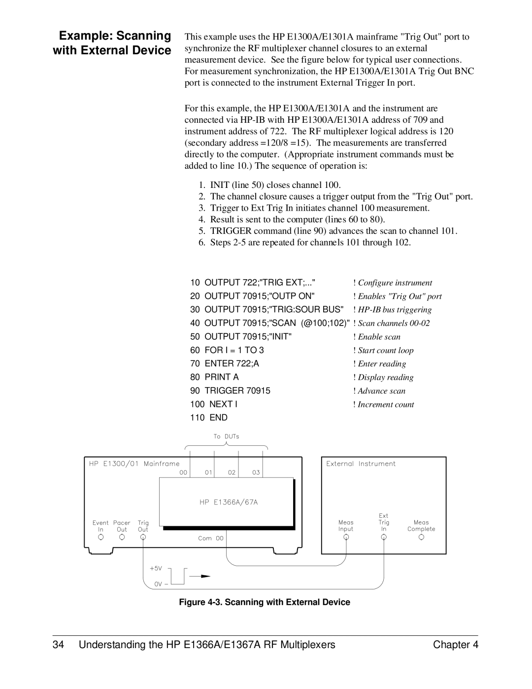
This example uses the HP E1300A/E1301A mainframe "Trig Out" port to synchronize the RF multiplexer channel closures to an external measurement device. See the figure below for typical user connections. For measurement synchronization, the HP E1300A/E1301A Trig Out BNC port is connected to the instrument External Trigger In port.
For this example, the HP E1300A/E1301A and the instrument are connected via
1.INIT (line 50) closes channel 100.
2.The channel closure causes a trigger output from the "Trig Out" port.
3.Trigger to Ext Trig In initiates channel 100 measurement.
4.Result is sent to the computer (lines 60 to 80).
5.TRIGGER command (line 90) advances the scan to channel 101.
6.Steps
10 | OUTPUT 722;"TRIG EXT;..." | ! Configure instrument |
20 | OUTPUT 70915;"OUTP ON" | ! Enables "Trig Out" port |
30 | OUTPUT 70915;"TRIG:SOUR BUS" | ! |
40 | OUTPUT 70915;"SCAN (@100;102)" | ! Scan channels |
50 | OUTPUT 70915;"INIT" | ! Enable scan |
60 | FOR I = 1 TO 3 | ! Start count loop |
70 | ENTER 722;A | ! Enter reading |
80 | PRINT A | ! Display reading |
90 | TRIGGER 70915 | ! Advance scan |
100 NEXT I | ! Increment count | |
110 END |
| |
Figure 4-3. Scanning with External Device
34 Understanding the HP E1366A/E1367A RF Multiplexers | Chapter 4 |