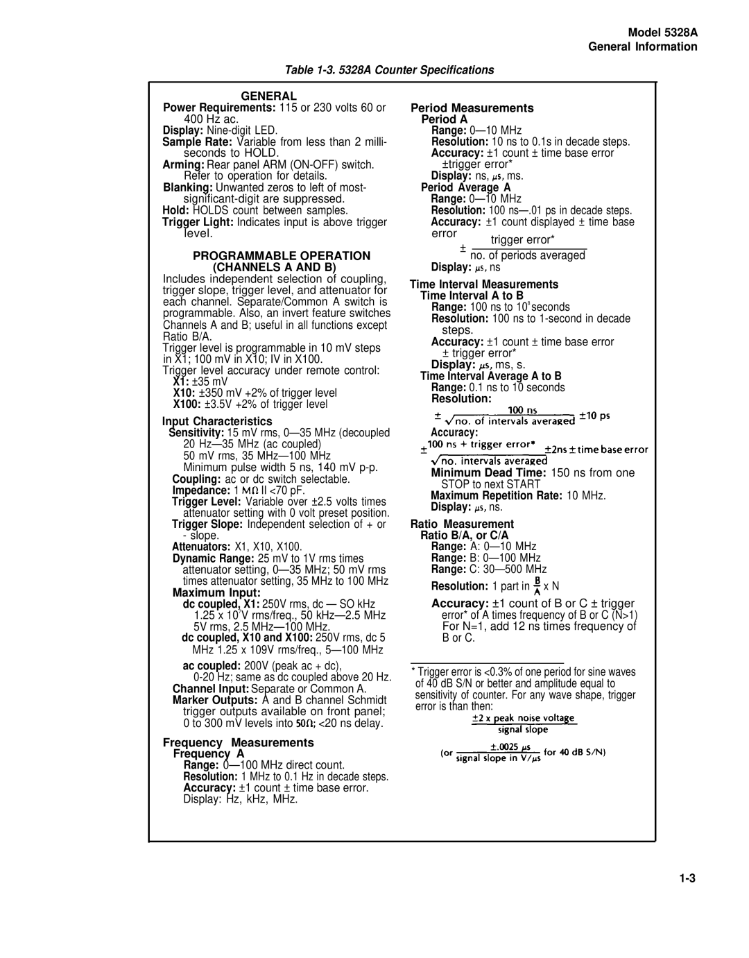
GENERAL
Power Requirements: 115 or 230 volts 60 or 400 Hz ac.
Display:
Sample Rate: Variable from less than 2 milli- seconds to HOLD.
Arming: Rear panel ARM
Blanking: Unwanted zeros to left of most-
level.
PROGRAMMABLE OPERATION (CHANNELS A AND B)
Includes independent selection of coupling, trigger slope, trigger level, and attenuator for each channel. Separate/Common A switch is programmable. Also, an invert feature switches Channels A and B; useful in all functions except Ratio B/A.
Trigger level is programmable in 10 mV steps in X1; 100 mV in X10; IV in X100.
Trigger level accuracy under remote control: X1: ±35 mV
X10: ±350 mV +2% of trigger level
X100: ±3.5V +2% of trigger level
Input Characteristics
Sensitivity: 15 mV rms,
50 mV rms, 35 MHz—100 MHz
Minimum pulse width 5 ns, 140 mV
Trigger Level: Variable over ±2.5 volts times attenuator setting with 0 volt preset position.
Trigger Slope: Independent selection of + or - slope.
Attenuators: X1, X10, X100.
Dynamic Range: 25 mV to 1V rms times attenuator setting,
Maximum Input:
dc coupled, X1: 250V rms, dc — SO kHz
1.25x 10⁷V rms/freq., 50
dc coupled, X10 and X100: 250V rms, dc 5 MHz 1.25 x 10⁹V rms/freq.,
ac coupled: 200V (peak ac + dc),
trigger outputs available on front panel; 0 to 300 mV levels into 50Q; <20 ns delay.
Frequency Measurements
Frequency A
Range:
Resolution: 1 MHz to 0.1 Hz in decade steps.
Accuracy: ±1 count ± time base error.
Display: Hz, kHz, MHz.
Period Measurements
Period A
Range:
Resolution: 10 ns to 0.1s in decade steps.
Accuracy: ±1 count ± time base error ±trigger error*
Display: ns, ps, ms.
Period Average A
Range:
Resolution: 100
Accuracy: ±1 count displayed ± time base
error trigger error*
± no. of periods averaged Display: Ps, ns
Time Interval Measurements
Time Interval A to B
Range: 100 ns to 108 seconds
Resolution: 100 ns to
Accuracy: ±1 count ± time base error
±trigger error* Display: ps, ms, s.
Time Interval Average A to B
Range: 0.1 ns to 10 seconds
Resolution:
Accuracy:
Minimum Dead Time: 150 ns from one STOP to next START
Maximum Repetition Rate: 10 MHz.
Display: Ps, ns.
Ratio Measurement
Ratio B/A, or C/A
Range: A:
Range: B:
Range: C:
Resolution: 1 part in ~ x N
Accuracy: ±1 count of B or C ± trigger error* of A times frequency of B or C (N>1) For N=1, add 12 ns times frequency of B or C.
*Trigger error is <0.3% of one period for sine waves of 40 dB S/N or better and amplitude equal to sensitivity of counter. For any wave shape, trigger error is than then:
