User Guide
User Notice
Ioline Flexjet E Printers
Table of Contents
Routine Maintenance
Glossary Index
Page
Page
Safety & Cautions
Visual Reference Guide
KM N
AB C D E F
Getting Started
Chapter
Ioline FlexJet E User Guide
How The Ioline FlexJet E and StudioJet printers Work
Unpacking the Printer
Printer Assembly
Assembling the Stand
Attaching the Printer to the Stand
COM Port
Serial Configuration
Cable Connections
Software Setup Options
Other Serial Port Settings
Installation
Baud Rate
CAD
Installing FlexPlot and the Control Center
Power On
This page intentionally left blank
Start/Stop
Keypad Controls
Set Origin
Clean
Quality
Special Key Combinations
Variety of settings are adjustable to fit specific needs
Changing System Settings
Control Center
Overview
File
Control Center Menu Bar Features
Communications
Tools
Control Center Menu Options
Consumables
Send marker/plot files
Printing a Marker
General Guidelines
Loading Paper on the FlexJet E
Loading Paper on the StudioJet
FlexJet E only
Installing the Take-up Shaft
2H+ FlexJet E
Feeding Paper
Positioning the Pinchwheels
Tape Paper to theTake-up Shaft
Positioning the pinchwheels
Insert Front Dancer Bar
Insert Rear Dancer Bar2H+ FJE Models Only
Pausing a Marker Plot
Set an Origin
Sending Plot Files
Removing Markers from the Take-up Shaft
Canceling a Marker Plot
Manually freeing the take-up shaft
Manually Freeing Take-up Shaft
Reattach Paper To the Take-up Shaft
Automatically Freeing the Take-Up Shaft
Printing to the Floor
Cleaning the Platen and Traverse
Cleaning the Drive Shaft
Prepare the Printer See the Operation chapter
Cleaning the Support Blocks
Size Calibration
Enter the Calibration Data
Click on Done when finished Routine Maintenance
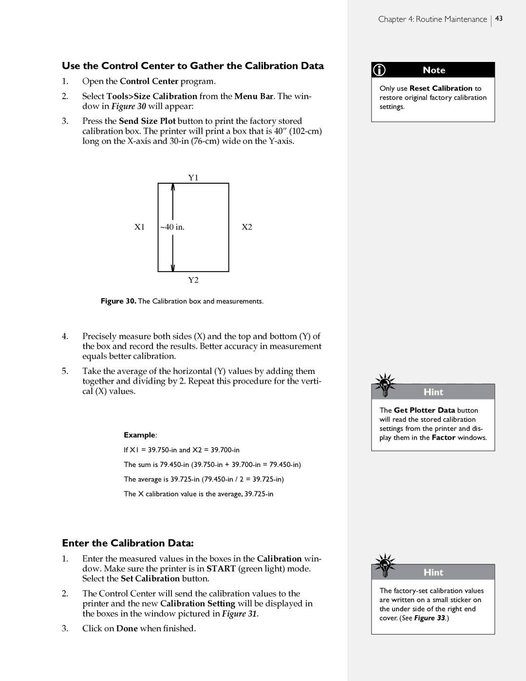
Use the Control Center to Gather the Calibration Data
Prepare the Printer
Cartridge Calibration
Frame Gap Paper Scan Alignment
Motion Adjust Carriage Scan Alignment
Click on Done when finished
Check Cartridges
Cartridge Maintenance and Handling
Automatic Cleaning Procedure
Open the latch for the first cartridge and remove it
Manual Cleaning Procedure
Soft, fiberless, and moistened with deionized water
Print Cartridge Storage
Update the Firmware
Reset Calibration Values
Media Tracking
General Troubleshooting
Serial Communication
Printing Quality
Line Quality
Troubleshooting
Keypad Error Codes
Printer does not complete the marker Cause
Common Issues
Quick Start Guide to level
Regular or intermittent paper tearing Cause
FlexJet E Models only
This page intentionally left blank
Getting Help
Service & Support
700 A.M. 500 P.M. U.S. Pacific Time
Customer Service
Your Comments Are Requested
End Notes
Before you contact Support…
This booklet is available from
FCC WantsYou to Know
Glossary
Panel See Frame
Glossary
This page intentionally left blank
Calibration 27, 42-46, 49
Clean ix, 24, 33, 41, 46
Arrow keys ix, 23, 24, 25, 37, 42, 44
DM/PL 15, 19, 20
Baud rate 18, 19, 25, 27, 28, 44, 52
Design software 15, 17, 19, 24, 28, 36, 51, 52, 54, 57, 61
File formats 15, 19, 20
Feed shaft x, 30, 31, 35, 42, 55, 63
EPS 27 PLT 27 PLX 27
Index
Set origin 24, 36, 37, 42, 44, 54, 56
Stalls xii, 29
Media 15, 16, 51
Origin 16, 21, 24, 36, 37, 42, 44, 53, 54, 56
Power switch xi, xiv, 21
Power cord xiv, 18, 21, 41
Platen xi, xii, xiii, 33, 41, 55, 56
Frame 16, 28, 54
Stop mode 23, 24, 25, 29, 37, 50
Service Station ix, xii, 21, 24, 33, 36, 46, 48, 50, 53
Sensor xii, 25
Serial port xi, xiv, 15, 17, 18, 19, 25, 52
USB xi Index
Traverse xii, 41
Unroll v, 23, 25, 32, 37, 39, 50
 43
43