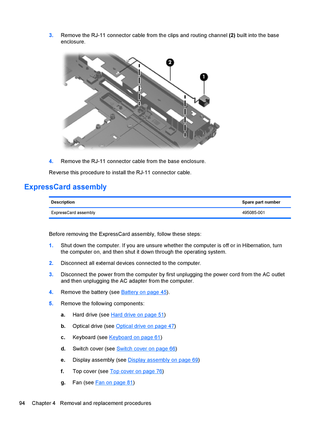
3.Remove the
4.Remove the
ExpressCard assembly
Description | Spare part number |
|
|
ExpressCard assembly | |
|
|
Before removing the ExpressCard assembly, follow these steps:
1.Shut down the computer. If you are unsure whether the computer is off or in Hibernation, turn the computer on, and then shut it down through the operating system.
2.Disconnect all external devices connected to the computer.
3.Disconnect the power from the computer by first unplugging the power cord from the AC outlet and then unplugging the AC adapter from the computer.
4.Remove the battery (see Battery on page 45).
5.Remove the following components:
a.Hard drive (see Hard drive on page 51)
b.Optical drive (see Optical drive on page 47)
c.Keyboard (see Keyboard on page 61)
d.Switch cover (see Switch cover on page 66)
e.Display assembly (see Display assembly on page 69)
f.Top cover (see Top cover on page 76)
g.Fan (see Fan on page 81)
94 Chapter 4 Removal and replacement procedures