Bottom components
Item | Component | Function |
|
|
|
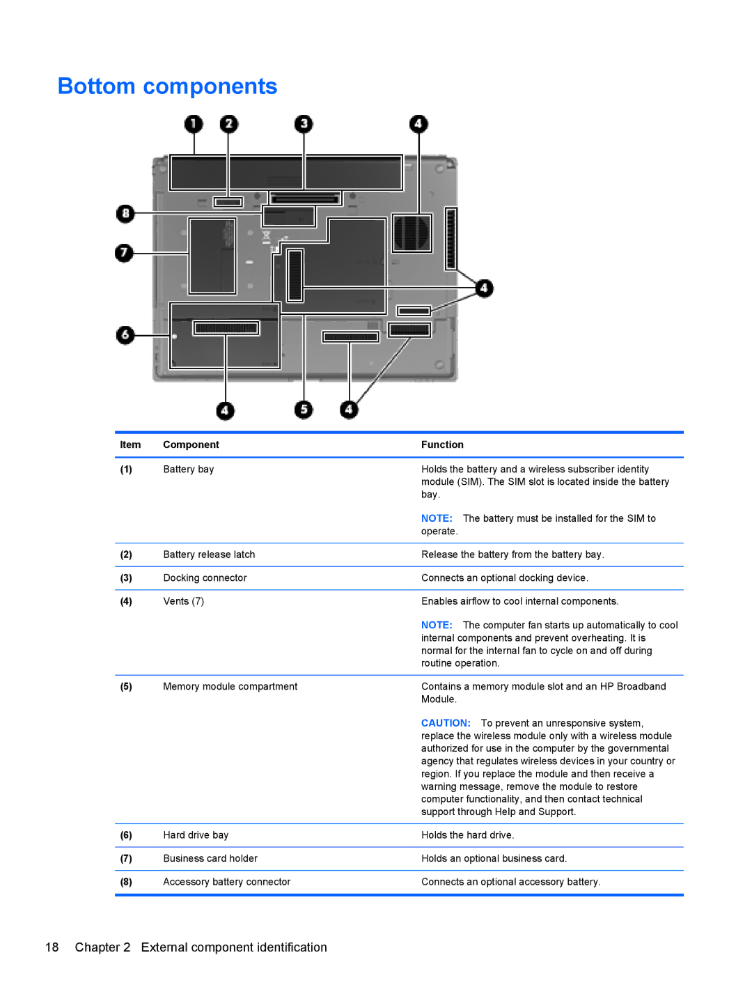
(1) | Battery bay | Holds the battery and a wireless subscriber identity |
|
| module (SIM). The SIM slot is located inside the battery |
|
| bay. |
|
| NOTE: The battery must be installed for the SIM to |
|
| operate. |
|
|
|
(2) | Battery release latch | Release the battery from the battery bay. |
|
|
|
(3) | Docking connector | Connects an optional docking device. |
|
|
|
(4) | Vents (7) | Enables airflow to cool internal components. |
|
| NOTE: The computer fan starts up automatically to cool |
|
| internal components and prevent overheating. It is |
|
| normal for the internal fan to cycle on and off during |
|
| routine operation. |
|
|
|
(5) | Memory module compartment | Contains a memory module slot and an HP Broadband |
|
| Module. |
|
| CAUTION: To prevent an unresponsive system, |
|
| replace the wireless module only with a wireless module |
|
| authorized for use in the computer by the governmental |
|
| agency that regulates wireless devices in your country or |
|
| region. If you replace the module and then receive a |
|
| warning message, remove the module to restore |
|
| computer functionality, and then contact technical |
|
| support through Help and Support. |
|
|
|
(6) | Hard drive bay | Holds the hard drive. |
|
|
|
(7) | Business card holder | Holds an optional business card. |
|
|
|
(8) | Accessory battery connector | Connects an optional accessory battery. |
|
|
|
18 Chapter 2 External component identification