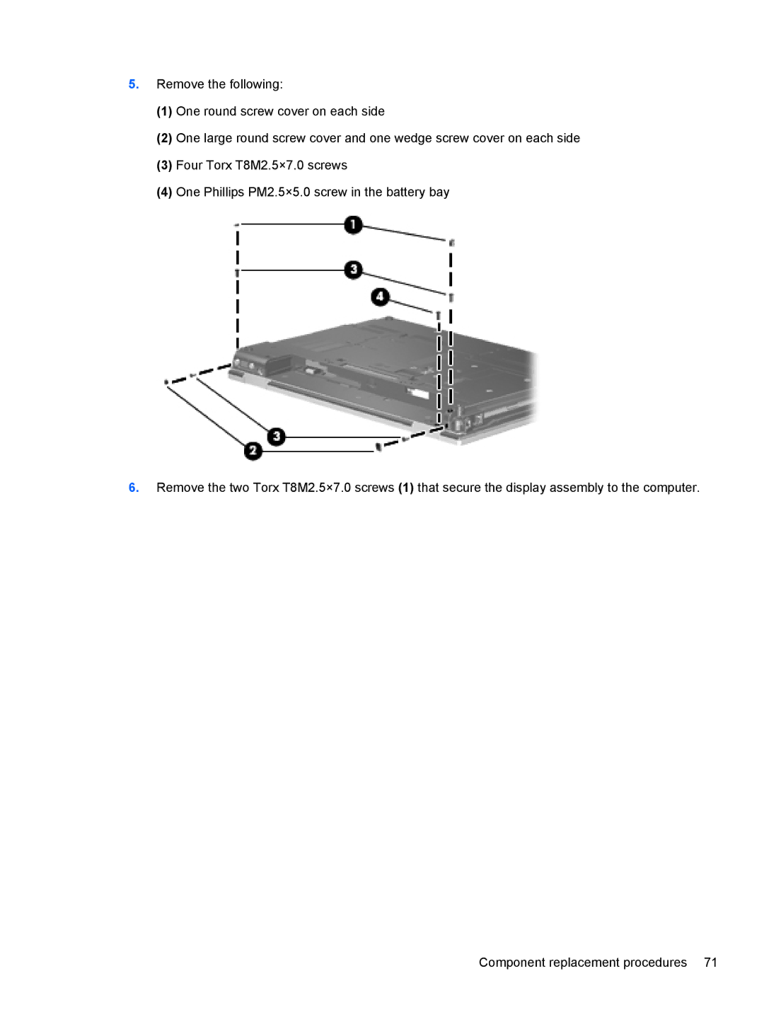
5.Remove the following:
(1)One round screw cover on each side
(2)One large round screw cover and one wedge screw cover on each side
(3)Four Torx T8M2.5×7.0 screws
(4)One Phillips PM2.5×5.0 screw in the battery bay
6.Remove the two Torx T8M2.5×7.0 screws (1) that secure the display assembly to the computer.
Component replacement procedures 71