Manuals
/
HP
/
Computer Equipment
/
Personal Computer
HP
HDX 16
manual
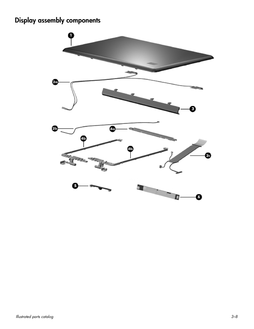
Display assembly components
Models:
HDX 16
1
27
146
146
Download
146 pages
41.45 Kb
24
25
26
27
28
29
30
31
Specification
Install
Bluetooth
Pin Signal
Password
Maintenance
System Configuration menu
Diagnostics menu
Access time
Setup Utility
Page 27
Image 27
Display assembly components
Illustrated parts catalog
3–8
Page 26
Page 28
Page 27
Image 27
Page 26
Page 28
Contents
HP HDX 16 Entertainment PC
Maintenance and Service Guide
Page
Safety warning notice
Contents
Setup Utility
11Recycling
Panel
Product description
Chipset
Graphics
Category Description Hard drives
Optical drives
Microphone
Modem
Wireless Integrated Wlan options by way of wireless module
Category Description Audio
Webcam
Category Description Ports
Power requirements
Operating system Preinstalled
Serviceability End-user replaceable parts
Component Function
External component identification
Top components
Display components
System and Maintenance Power Options
Buttons, speakers, and fingerprint reader
Support
Component Function
Keys
Component Function Esc key
Fn key
Lights
Sound Mouse
Pointing devices
Front components
Right-side components
Component Function USB ports Connect optional USB devices
Rear component
Left-side components
Bottom components
Service tag
Illustrated parts catalog
Component Description
Computer major components
Bluetooth module cable
Switch cover
Power button board includes cable
Bluetooth module
TouchPad on/off button board incudes cable
Speaker assembly
Battery
Description Spare Part Number Base enclosure, includes
RTC battery
TV tuner module
TV tuner external antenna cable not illustrated
Description Spare Part Number Wlan module
Description Spare part number Plastics Kit 496477-001
Plastics Kit
Display assembly components
Display Hinge Kit, includes
Description Spare part number Display enclosure
Display Cable Kit, includes
Display hinge cover
Mass storage devices
Miscellaneous parts
Spare part number Description
Sequential part number listing
Cable, and display panel cable
Spare part number Description
Spare part number Description
Spare part number Description
Tools required
Removal and replacement procedures
Preliminary replacement requirements
Service considerations
Drive handling
Grounding guidelines
Packaging and transporting guidelines
Workstation guidelines
Material Use Voltage protection level
Unknown user password
Service tag
Component replacement procedures
Computer feet
Battery
Optical drive
Removal and replacement procedures
Hard drive
Removal and replacement procedures
TV tuner module
Description Spare part number RTC battery 449729-001
RTC battery
Memory module
Wlan module
Reverse this procedure to install the Wlan module
Description Spare part number Switch cover 496471-001
Switch cover
Removal and replacement procedures
Keyboard cover
Removal and replacement procedures
Power button board
Description Spare part number Bluetooth module 483113-001
Bluetooth module
Keyboard
Removal and replacement procedures
Removal and replacement procedures
Power button board cable
Bluetooth module cable
LED board cable
Description Spare part number Speaker assembly 496476-001
Speaker assembly
Display assembly
Removal and replacement procedures
Removal and replacement procedures
Removal and replacement procedures
Removal and replacement procedures
Removal and replacement procedures
Removal and replacement procedures
Removal and replacement procedures
Top cover
Removal and replacement procedures
Removal and replacement procedures
Removal and replacement procedures
TouchPad on/off button board
Removal and replacement procedures
496460-001
System board
Removal and replacement procedures
Removal and replacement procedures
Description Spare part number Fan 514290-001
Fan
Removal and replacement procedures
Audio/infrared board
Removal and replacement procedures
TV tuner module cable
USB board
Power connector cable
Removal and replacement procedures
Subwoofer
Removal and replacement procedures
Fan/heat sink assembly
Remove the fan/heat sink assembly
Removal and replacement procedures
Processor
Removal and replacement procedures
Navigating and selecting in the Setup Utility
Setup Utility
Starting the Setup Utility
Changing the language of the Setup Utility
Displaying system information
Restoring default settings in the Setup Utility
Using advanced Setup Utility features
Closing the Setup Utility
Security menu
Setup Utility menus
System Configuration menu
Main menu
Primary Hard Disk Self Test
Diagnostics menu
Computer specifications
Specifications
Inch HD display specifications
Inch FHD display specifications
Hard drive specifications
Hard drive specifications 250-GB 160-GB Dimensions
Cache buffer Data transfer rate
Blu-ray ROM DVD±RW SuperMulti DL Drive specifications
Access time
Applicable disc Read Write
CD-RW, Dvdrom DVD-5
Size Memory address System function
System DMA specifications
System memory map specifications
Hardware DMA System function
Hardware IRQ System function
System interrupt specifications
Address hex System function shipping configuration
System I/O address specifications
EF80-EF9F
Screw listing
Phillips PM2.5×7.0 screw
Color Quantity Length Thread Head diameter Black
Where used
Screw listing
Phillips PM2.0×4.0 screw
Where used
Screw listing
Screw listing
Screw listing
Screw listing
Phillips PM2.5×6.0 captive screw
Color Quantity Length Thread Head diameter Silver
Phillips PM3.0×4.0 screw
Phillips PM2.5×5.0 broadhead screw
Color Quantity Length Thread Head diameter Silver 11.0 mm
Phillips PM2.5×11.0 captive screw
Phillips PM2.5×5.0 captive screw
Backup and recovery
Recovering system information
Creating recovery discs
When to back up
Backup suggestions
Backing up your information
When to create restore points
Using system restore points
Recovering from the recovery discs
Performing a recovery
Audio-in microphone
Connector pin assignments
Pin Signal
1394
External monitor
Audio-out headphone
Hdmi
Universal Serial Bus
RJ-45 network
Requirements for all countries and regions
Power cord set requirements
Country/region Accredited agency Applicable note number
Requirements for specific countries and regions
Battery
Recycling
Display
11-2
11-3
11-4
11-5
11-6
Index
Index-2
Esc 2-4fn 2-4function
Index-4
Index-5
Top
Page
Image
Contents