Removal and Replacement Procedures
5.2 Disassembly Sequence Chart
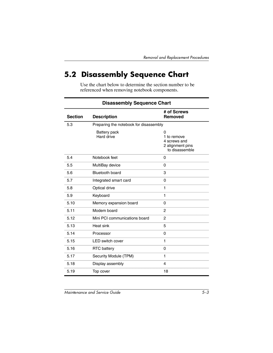
Use the chart below to determine the section number to be referenced when removing notebook components.
Disassembly Sequence Chart
|
| # of Screws |
Section | Description | Removed |
5.3Preparing the notebook for disassembly
| Battery pack | 0 |
| Hard drive | 1 to remove |
|
| 4 screws and |
|
| 2 alignment pins |
|
| to disassemble |
|
|
|
5.4 | Notebook feet | 0 |
|
|
|
5.5 | MultiBay device | 0 |
|
|
|
5.6 | Bluetooth board | 3 |
|
|
|
5.7 | Integrated smart card | 0 |
|
|
|
5.8 | Optical drive | 1 |
|
|
|
5.9 | Keyboard | 1 |
|
|
|
5.10 | Memory expansion board | 0 |
|
|
|
5.11 | Modem board | 2 |
|
|
|
5.12 | Mini PCI communications board | 2 |
|
|
|
5.13 | Heat sink | 5 |
|
|
|
5.14 | Processor | 0 |
|
|
|
5.15 | LED switch cover | 1 |
|
|
|
5.16 | RTC battery | 0 |
|
|
|
5.17 | Security Module (TPM) | 1 |
|
|
|
5.18 | Display assembly | 4 |
|
|
|
5.19 | Top cover | 18 |
|
|
|
Maintenance and Service Guide |