Drop boxes
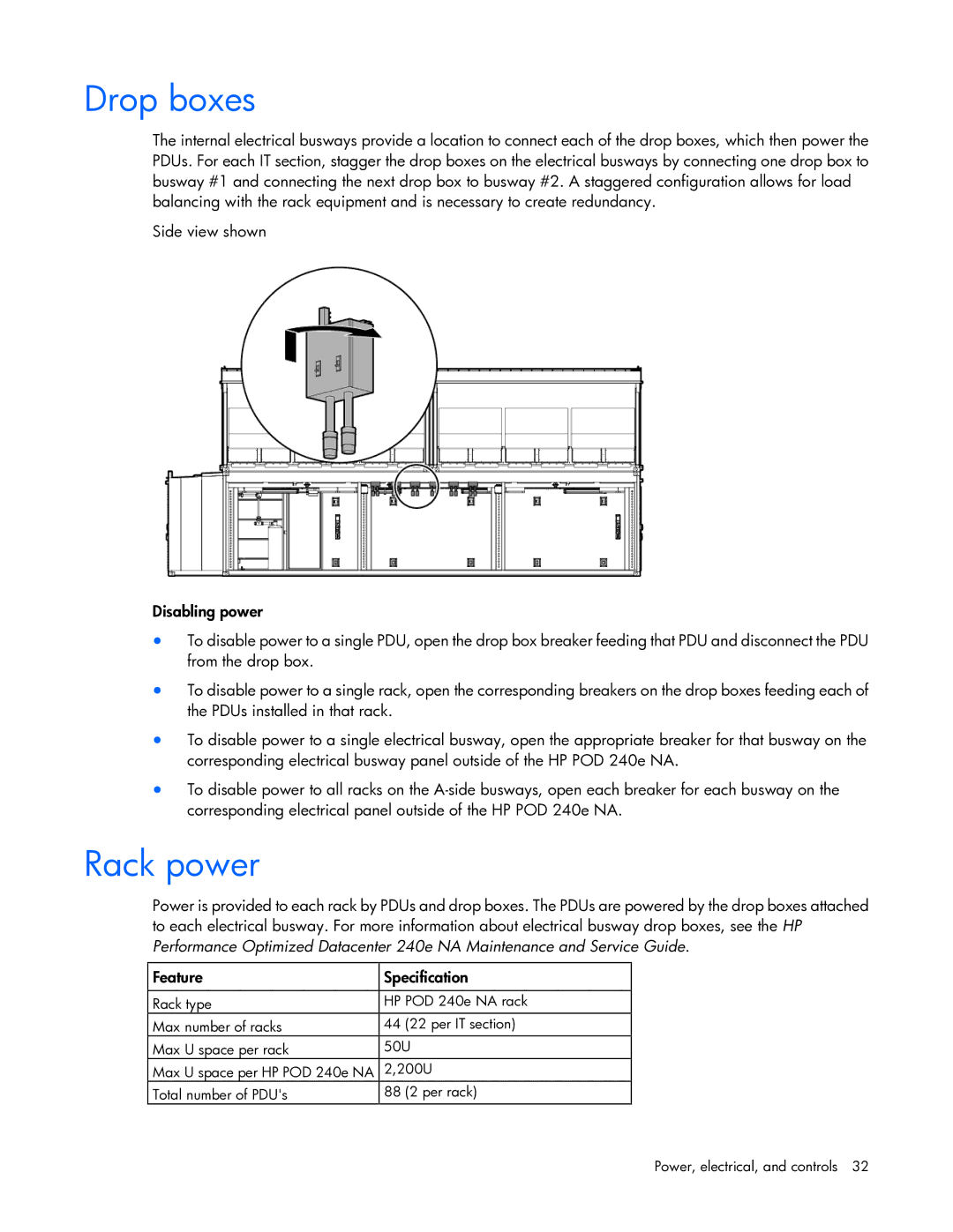
The internal electrical busways provide a location to connect each of the drop boxes, which then power the PDUs. For each IT section, stagger the drop boxes on the electrical busways by connecting one drop box to busway #1 and connecting the next drop box to busway #2. A staggered configuration allows for load balancing with the rack equipment and is necessary to create redundancy.
Side view shown
Disabling power
•To disable power to a single PDU, open the drop box breaker feeding that PDU and disconnect the PDU from the drop box.
•To disable power to a single rack, open the corresponding breakers on the drop boxes feeding each of the PDUs installed in that rack.
•To disable power to a single electrical busway, open the appropriate breaker for that busway on the corresponding electrical busway panel outside of the HP POD 240e NA.
•To disable power to all racks on the
Rack power
Power is provided to each rack by PDUs and drop boxes. The PDUs are powered by the drop boxes attached to each electrical busway. For more information about electrical busway drop boxes, see the HP Performance Optimized Datacenter 240e NA Maintenance and Service Guide.
Feature | Specification |
|
|
Rack type | HP POD 240e NA rack |
Max number of racks | 44 (22 per IT section) |
Max U space per rack | 50U |
Max U space per HP POD 240e NA | 2,200U |
Total number of PDU's | 88 (2 per rack) |
Power, electrical, and controls 32