Item | Component | Description |
|
|
|
4 | Filter box | Louvers and dampers provide an outside air inlet of each Adiabatic unit. If the |
|
| outside air temperature and humidity conditions are within the correct range of |
|
| the operating envelope, the dampers open automatically when the AHU is |
|
| powered on. |
|
|
|
5 | Power disconnect | The main power supply switch for each Adiabatic unit |
| switch |
|
6 | Electrical controls box | Houses the electrical controls and components |
*Use the lifting eyes on top of the unit to lift the Adiabatic unit. Do not lift the Adiabatic unit with the lifting eyes installed on the filter box.
Adiabatic media
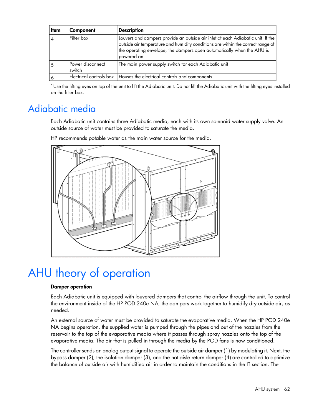
Each Adiabatic unit contains three Adiabatic media, each with its own solenoid water supply valve. An outside source of water must be provided to saturate the media.
HP recommends potable water as the main water source for the media.
AHU theory of operation
Damper operation
Each Adiabatic unit is equipped with louvered dampers that control the airflow through the unit. To control the environment inside of the HP POD 240e NA, the dampers work together to humidify dry outside air, as needed.
An external source of water must be provided to saturate the evaporative media. When the HP POD 240e NA begins operation, the supplied water is pumped through the pipes and out of the nozzles from the reservoir to the top of the evaporative media where it passes through spray nozzles onto the top of the evaporative media. The air that is pulled in through the media by the POD fans is now conditioned.
The controller sends an analog output signal to operate the outside air damper (1) by modulating it. Next, the bypass damper (2), the isolation damper (3), and the hot aisle return damper (4) are controlled to optimize the balance of outside air with humidified air in order to maintain the conditions in the IT section. The
AHU system 62
