HP E1432A User's Guide
Using the HP E1432A
In the BOOTING state, the digital processors of the module load their parameters, and their program. Once done, the module releases the Sync/Trigger line and moves to the BOOTED state. The HP E1432A stays in the BOOTED state until it sees a
In the SETTLING state, the digital filters are synchronized, and the digital filter output is ‘settled’ (it waits N samples before outputting any data). Once the module is settled, it advances to the PRE_ARM state.
In the PRE_ARM state, the module waits for a
This complete measurement sequence initialization, from TESTED through BOOTING, BOOTED, SETTLING,
Measurement Loop
This section describes the measurement loop in the HP E1432A.
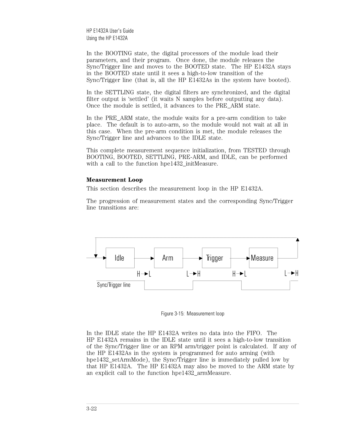
The progression of measurement states and the corresponding Sync/Trigger line transitions are:
Idle
H ![]() L
L
Sync/Trigger line
Arm
Trigger
L ![]() H
H
 Measure
H  LL
LL  H
H
Figure 3-15: Measurement loop
In the IDLE state the HP E1432A writes no data into the FIFO. The
HP E1432A remains in the IDLE state until it sees a