HP E1432A Channel 51.2 kSa/s Digitizer plus DSP User’s Guide
Warranty
This Book
HP E1432A Users Guide
Page
Table of Contents
Using the HP E1432A
C-Language Host Interface Library
Arbitrary Source Option 1D4
Troubleshooting the HP E1432A
Page
Installing the HP E1432A
To inspect the HP E1432A
Installing the HP E1432A
HP E1432A Users Guide Installing the HP E1432A
To install the HP E1432A
Page
Set the mainframe’s power switch to standby O
Install the host interface libraries
To store the module
To transport the module
Page
Getting Started With the HP E1432A
Introduction
HP E1432A Users Guide Getting Started With the HP E1432A
To install the VXIplug&play libraries
System Requirements Microsoft Windows95 and NT
System Requirements HP-UX
One of the following workstations
Getting Updates Via FTP HP-UX
Getting Updates Via FTP Windows
HP E1432A Users Guide Getting Started With the HP E1432A
Resource Manager
Using the soft front panel
VXIplug&play Soft Front Panel SFP
There is a checkbox to make all channels identical
Use the Exit button to exit the Soft Front Panel
HP VEE example programs
Scope.vee
Scope.vee panel view
HP VEE
Scope.vee detail view
Minimum.vee
Minimum.vee scroll to see entire display
Other HP VEE example programs
Language Host Interface Library example programs
Demo Programs
Running a demo program semascope.c
Visual Basic example programs
Page
Using the HP E1432A
HP E1432A Users Guide Using the HP E1432A
VXIplug&play drivers
What is VXIplug&play?
Overview
Manufacturer and model codes
Model Name
Soft Front Panel SFP
An example of a soft front panel SFP
Header and Library Files
Initialization
Channels and groups
Channel Groups
Creating a Channel Group
Input, Source, and Tach Channels
Multiple-module Measurements
Multiple-module/mainframe Measurements
Grouping of Channels/Modules
Possible Trigger Line Conflict
Managing Multiple-mainframe Measurements
Slot HP E1482B HP E1432A Contoller
Phase Performance in Multiple Mainframe Measurements
Multiple mainframes three mainframes
Synchronization in Multiple-mainframe Measurements
Module Features
Data Flow Diagram and Fifo Architecture
Host port
Ch 1 Input
Trigger
ADC
Base Sample Rates
Sample
32000 32768 40000 40960
With ÷5 Without ÷5
With ÷5
Additional Notes on Measurement Spans
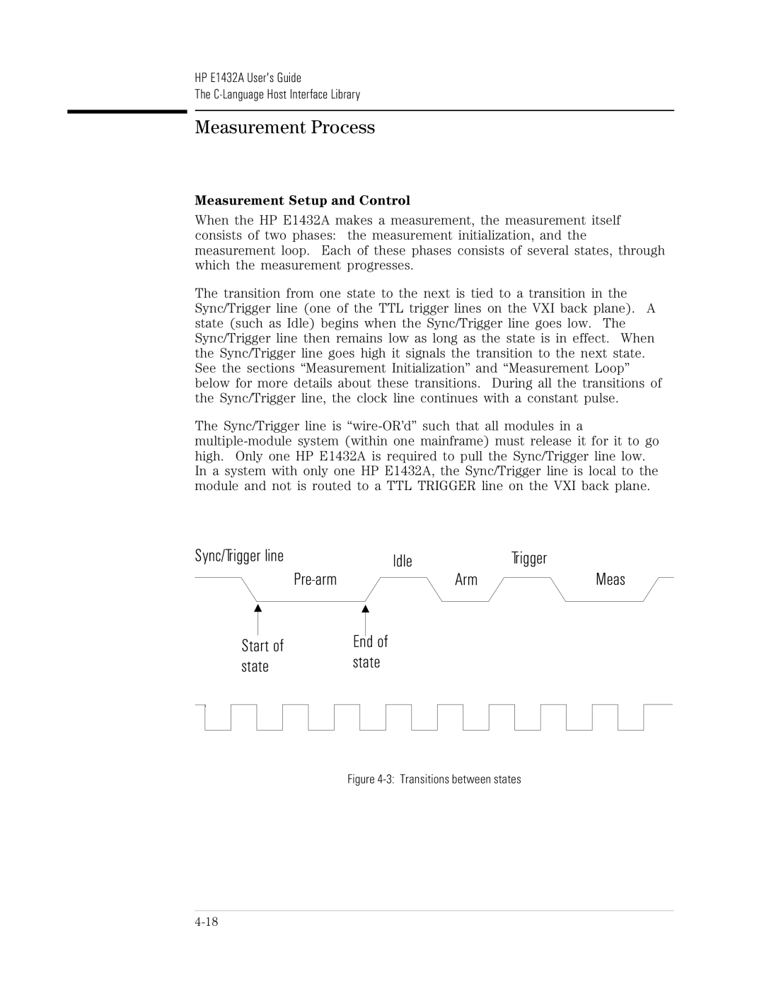
Measurement Setup and Control
Measurement Process
Parameter Settings
Measurement Initiation
Measurement Loop
Idle
Arm Trigger Measure LL H
Register-based VXI Devices
Arm and Trigger
Valid trigger conditions are
HP E1432A Triggering
Auto Trigger circuitry
Source trigger
Tach trigger
Trigger Level
Data Transfer Modes
Limit on Queuing of Data
HP E1432A Interrupt Behavior
Scan of data ready in Fifo Fifo overflow
This is a summary of how to set up an HP E1432A interrupt
Data Gating
HP E1432A Parameters
HP E1432A Users Guide Using the HP E1432A
New features of the HP E1432A/HP E1433A software
Zoom HP E1432A only
Zoom for the Arbitrary Source, option 1D4
Where to get more information
Function Reference for VXIplug&play
Page
C-Language Host Interface Library
HP E1432A Users Guide C-Language Host Interface Library
Header and Library Files
Parameter Information
Description of HP E1432A Parameters
Parameter Lists
Datasize Bit Integer Abort Decimationoutput Single Pass Wait
Ttltrgtrigger
Ttltrggclock
Ttltrgsatrg
KHz 4-channel Input Parameters
Option 1D4 Single-channel Source Parameters
Option AYF Tachometer Parameters
Channel and Group IDs
Group IDs
Multiple-module/Mainframe Measurements
Possible Trigger Line Conflict
HP E1482B HP E1432A
Phase Performance in Multiple Mainframe Measurements
Intx
Synchronization in Multiple-mainframe Measurements
Sync/Trigger line Idle
Measurement initialization
Measurement loop
Register-based VXI Devices
Arm and Trigger
Trigger type Enabling function
An external trigger E1432settriggerext
Data Transfer Modes
Limit on Queuing of Data
Non-fatal measurement warning
Block of data ready in Fifo
Overload status changed
Raw tach-times available
HP E1432A Interrupt Handling
Data Gating
For More Information
Page
Module Description
General Features
Arbitrary Source Features option 1D4
Tachometer Features option AYF
HP E1432A Users Guide Module Description
Block Diagram
Source
VXI Mainframe HP E1432A Other VXI Modules
ADC
HP E1432A Front Panel Description
Front Panels for 4, 8, and 16 Channels
Standard Front Panel
10 HP E1432A standard front panel
Status LEDs
VXI Backplane Connections
Local Bus Option UGV
HP E1432A VXI Device
Address Space
Shared Memory
Memory Map
Movable DSP
Bus Window
Fixed DSP
Send/Receive
List of A16 Registers
Read Write
Sync
Trigger Lines Ttltrg
Clock
Providing an External Clock
Calibration Description
Input circuitry
Page
Arbitrary Source Option 1D4
Arbitrary Source Description
DAC
Arbitrary Source Option Front Panel
14 HP E1432A with source option front panel
LED’s and Connectors for the Arbitrary Source Option
Updating the arbitrary source firmware
Page
Tachometer Option AYF
Tachometer Description
Tachometer Inputs
External Trigger Input
Tachometer Monitoring
Input Count Division
Holdoff Time
Tachometer Option Front Panel
16 HP E1432A with tachometer front panel
LED’s and Connectors for the Tachometer Option
Page
Break Out Boxes
Service
HP E1433A Users Guide Break Out Boxes
HP E1432-61600 and HP E1432-61602 Break Out Boxes
17 HP E1432-61602 Voltage Break Out Box
Break Out Box Grounding
HP E1432-61602 Voltage-type Break Out Box
HP E1432-61600 ICP-type Break Out Box
Break Out Box Cables
Making a Custom Break Out Box Cable
Pin
Pin #
RFI GND/Cable Shield
23 -24 V Power 24 +/-24 V GND Return 25 +24 V Power
Calhigh
Troubleshooting the HP E1432A
Diagnostics
HP E1432A Users Guide Troubleshooting the HP E1432A
HP E1432A Users Guide Troubleshooting the HP E1432A
Page
Replacing Assemblies
Replaceable Parts
HP E1432A Users Guide Replacing Assemblies
Ordering Information
Direct Mail Order System
Code Numbers
Assemblies without option AYF or 1D4
28480 E1432-66502
28480 E1432-66504 A10
28480 E1433-66510 A11
28480 E1432-00601
Assemblies with option AYF
E1432-66505
A22 1818-5622 ICM DRAM, Simm
A24 1818-5624 ICM DRAM, Simm
MP001
Assemblies with option 1D4
A41
E1432-66541
Cables without option AYF or 1D4
Description Mfr Mfr Part Number Code
Cables with option AYF
CBL-ASM CXL
Cables with option 1D4
Front Panel
To remove the top cover
To remove the front panel
10-16
10-17
To remove the input assemblies
10-19
To remove the option AYF assembly
To remove the option 1D4 assembly
To remove the A22/A24 assembly
To remove the A1/A11 assembly
10-24
Backdating
HP E1432A Users Guide Backdating
Main PC assembly change
Backdating
Appendix a
A16 Registers
HP E1432A VXI Registers
HP E1432A Users Guide Register Definitions
Write
A24 Registers
Bit 15-14 13-12 11-0
111111111111
HP’s ID
Bit 15-8
HP E1432A Users Guide Register Definitions
Bit 14-2
Bit 15-2
Line
Bit DSP A17 DSP A18 DSP A19 DSP A20 DSP A21 DSP A22
Bit DSP A31
Contents Status Logical
Bit Registers
Writing 32-bit Registers
Command/Response Protocol
Command/Response protocol uses the following resources
Controller Protocol Examples
DSP Protocol
DSP Command Register Boot Register
DSP Bus Registers
200A
Bit 31-16
Bit 31-24
HP E1432A
81.25
42Vp
12510-6
01%fs,− 90dBfstypical
AliasedResponses
Output
244∝Hz
Spuriousresponses
Vpnominal
Two
TimcanbesettoavoidflseìTachtri
ÌHoldoffîOnethe
Calibratianalogpath
WistaardndowsforHP-UX,MSWindows95and
IECISPR11190,Group1,ClassA
Humdity,Non-condensing 20%RH90%RHat40C
Edtoncompliance,1978
Sourceoptioninstalled
03A
2MB/s
0MB/sto15.7MB/s
Glossary
HP 1432A Users Guide Glossary
Digital Signal Processing
Interrupt ReQuest
Random Access Memory
Static Random Access Memory
VME Bus
Page
Index
HP 1432A Users Guide Index
Cola
HP Sicl HP VEE
LEDs 5-7, 6-5
HP 1432A Users Guide Index
VXI
HP 1432A Users Guide Index
Page
Need Assistance?
Page
Declaration of Conformity
Cathy Thran, Quality Manager
Page
About this edition