Hardware Maintenance Service for Service Level a
Page
Contents
Electrical input Operating Requirements
Check Procedures
Diagnostic Aids
System Backup Battery
Parts/Test Point Locations
Safety Inspection Guide
Parts Catalog
Appendix B. Online Support
Appendix A. FRU Number List
Index
Voltage Supply Range Voltage Switch Setting
Voltage Supply Switch Settings
To Connect To Disconnect
Safety Information
Do not
Para Desconectar
Para Conectar
Cuidado
Cuidado
Page
Xiv
Page
Xvi
Connexion Déconnexion
Xviii
Page
Kabel anschließen Kabel lö sen
Vorsicht
Achtung
Xxii
Instrumenten betrachten und den Strahlungsbereich meiden
Per collegare Per scollegare
Pericolo
Xxiv
Attenzione
Attenzione
Xxvi
Page
Instrucciones de Conexió n Desconexió n
Xxviii
Peligro
Page
Categorie
Laser Compliance Statement
HelpCenter
Trademarks
Appendix A, FRU Number Index contains part
Preface
Numbers listed in numerical order
Xxxiv
General Information
Introduction
Processor
Product Overview
Memory
Diskette Drive
External Port
Hard Disk Drive
DVD-ROM Drive
Power Management
Multimedia
Internal Cabling
Power Supply
Monitor Not included with some models
Mouse
Keyboard
Interface
Hardware Interfaces
USB
Cmos Reset
Power-On Password
Flash Bios Update Procedure
Type ADMICFG.EXE/ type 01 05 Type
BIOS-contained Model Number and Serial Number
Working with the Configuration/Setup Utility Menu
Bios Configuration/Setup Utility
Keys Function
Changing Parameter Settings
Save & Exit Settings
Devices and I/O ports
Viewing System Information, and Product Data
Onboard Parallel Port
Onboard Parallel Mode
ECP Mode Use DMA
Onboard Serial Port
Onboard Sound
IDE Prefetch Mode
MPU-401 --Enabled
USB Mouse Support
Startup Options
Keyboardless Operation
Setting a Power-On Password
Delete Power-On Password
Changing the Power-On Password
External Cache
Advanced Setup
Video Bios Shadow
CPU Internal Cache
Power Management Setup
PM Control by APM
HDD Power Down
Doze Mode
Suspend Mode
Activity Monitor
Video Off Method
Primary Intr
Date Month
Power On by PCI Card
RTC Alarm Resume
Modem Ring Resume
Page
Specifications
Operating Requirements
Check Procedures
Index of Symptoms, Messages, Error Codes, or
Start
Read the Following
Insert diagnostics diskette in the diskette drive
007
005
009
Index of Symptoms, Messages, Error Codes, or Beeps
Page
Bios Error Codes Action/FRU Messages
Post Error Codes and Messages List
Post Error Codes and Messages List
Post Error Codes and Messages List
Post Error Codes and Messages List
Bios Error Beeps Action/FRU
Bios Error Beeps List
Error Symptoms Action/FRU Processor / Processor Fan
Error Symptoms List
System Board and Memory
Diskette Drive
Error Symptoms Action/FRU
Check Procedures
CN6 HDD
Hard Disk Drive
Error Symptoms Action/FRU CD/DVD-ROM Drive
Date and Time on
Video and Monitor
Keyboard
Diagnostic Program
Parallel/Serial Ports
Joystick
Other Problems
Error Symptoms Action/FRU Power Supply
Factory-Installed Storage Devices
Troubleshooting
Select Utility from the menu
003
005
Page
002
Factory-Installed Modem Card
Modem adapter functions normally End
Select Program, then select Accessories, Hyper Terminal
Select an on-line service station, dial and connect to it
Start Microsoft Windows Select the Start icon
Audio Not Supported by Diagnostics Program
008
Select Settings, then select Control Panel
004
006
Page
CD/DVD-ROM Drive
Replace CD/DVD-ROM drive End IBM Desktop System HMM
Replace system board End
Follow the screen instructions to run the Memory test
Memory
Replace the system board End
Keyboard
Keyboard is functioning normally End
Try with a known good keyboard
Mouse is functioned normally End
Mouse
Test right left button and check if right left button works
Test mouse cursor movement
011
Try with a known good mouse
010
Replace the mouse End
Disconnect the power cord from the back of the system unit
Power Supply
Pin-hole side view
Replace the power supply End Check Procedures
Replace the on/off switch cable assembly
Monitor
Is the Screen READABLE? YES, Read AHEAD. NO, GO to Step
Dimm
Undetermined Problems
Page
IBM Desktop System HMM
Diagnostic Aids
Introduction
Power-On Self Test
Page
Using the Diagnostic Diskette
Diagnostic Diskette
Using Diagnostic Program from Recovery CD
Submenu Selections
Diagnostics Program Features
Diagnostic Program Main Menu Selections
Repair Information
Removals and Replacements
Handling ESD-Sensitive Parts
Bay
Identifying the Parts of the System Unit
Adapter card slots
Adapter card connectors
Power supply
Adapter cards
Cover
Page
Bay Panels
Bay 1- 5.25-In. Bay Internal or External Access
Page
Page
Front Panel
Power Supply
Adapter Cards
MemoryDIMM
AMD K7 Duron Processor
Page
System Backup Battery
Indicator LED and Cable
System Board
Page
IBM Desktop System HMM
Parts/Test Point Locations
Parts/Test Point Locations
Introduction
Jumper/Settings Function
System Board Jumpers Connectors
System Board Jumper Setting
System Board Connector Functions
CN6
Power Supply Output Pin Assignment
Power Supply Connectors and Voltages
Pin Voltage Cable Color
+5Vdc Green Ground Black No connect Red
Network Cards
RJ-45 connector is used Accton Parts/Test Point Locations
Askey GVC Factory-Installed Modem Card Connector Functions
Factory-Installed Modem Card Layout
Function Connect to RJ11 connector Telephone line
Nvidia M64 w/ TV Out, 32MB Nvidia NV10 w/ TV Out, 32MB
Video Cards
Pin Signal
D Signal Pin Assignments
Optional output from monitor IBM Desktop System HMM
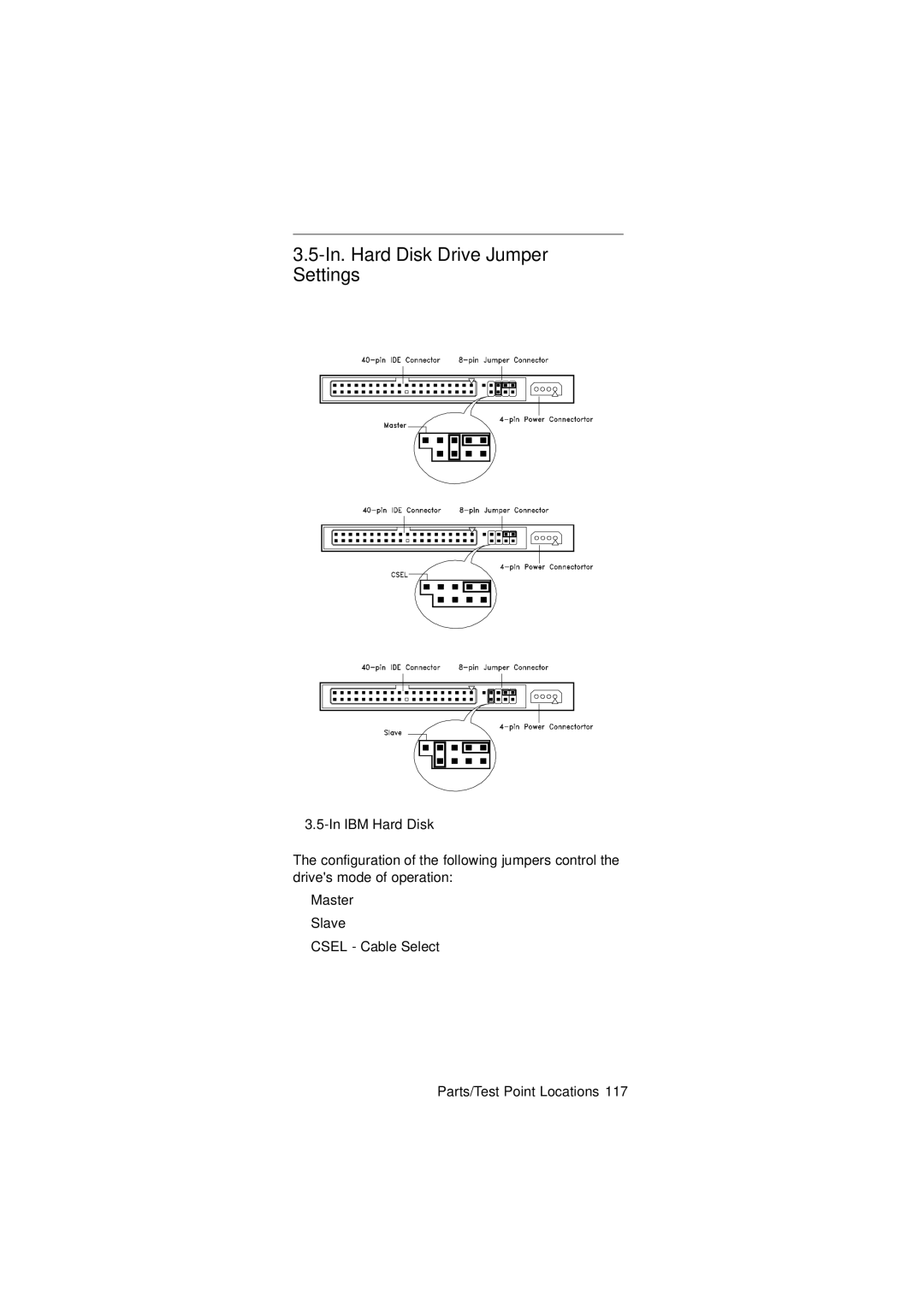
In. Hard Disk Drive Jumper Settings
J50 Description
Lite-on
CD-ROM Drive
CD-ROM Emergency-exit option
CD-ROM Front Panel Introduction
CD-ROM Drive Rear Panel Connectors and Jumpers
CD-ROM Drive Rear Panel Connectors and Jumpers
Function Connect to
CD-ROM R/W Front Panel Introduction
CD-ROM R/W Drive
CD-ROM R/W Drive Rear Panel Connectors and Jumpers
DVD-ROM Front Panel Introduction
DVD-ROM Drive Front Panel and Emergency-Exit
DVD-ROM Drive Rear Panel Connectors and Jumpers
DVD-ROM Drive Rear Panel Connectors and Jumpers
Function Connect
Dimm Configurations
Pin Signal Name
System Board Connector Pin Signals
Monitor Port Signals
Serial Port Signals
Mouse Port Signals
Parallel Port Signals
Keyboard Port Signals
Diskette Drive Cable Connector Signals
IDE Cable Connector Signals
Safety Inspection Guide
General Guidelines
Parts Catalog
Parts Catalog
Country Language Version
Abbreviations
Index Number
System Assembly
Assembly 1 System Uni
Asm
IBM Desktop System HMM
Assembly 2 Diskette, Hard Drive and Zip Drive
Assembly 3 CD/DVD-ROM Drive
Assembly 4 Power Cord
Assembly 5 Keyboard and Mouse
FRU Number Asm-Index
FRU Number List
20L2197
Online Support
Appendix B. Online Support Information
Page
Index
Audio Check Procedure
Page
Page