Chapter 2 Installations
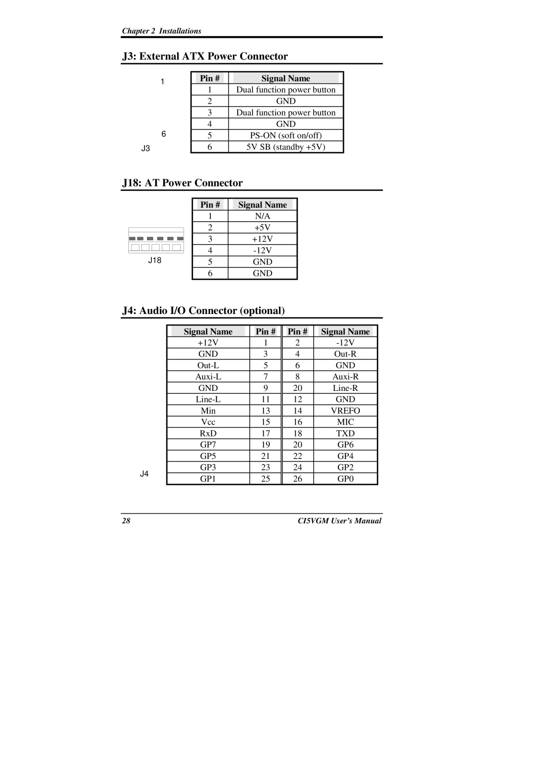
J3: External ATX Power Connector
1 |
| Pin # |
|
|
| Signal Name |
|
| 1 |
|
| Dual function power button |
| ||
|
|
|
|
| |||
|
| 2 |
|
|
| GND |
|
|
| 3 |
|
| Dual function power button |
| |
6 |
| 4 |
|
|
| GND |
|
| 5 |
|
|
| |||
J3 |
| 6 |
|
| 5V SB (standby +5V) |
| |
J18: AT Power Connector
J18 |
| Pin # |
|
| Signal Name |
|
| 1 |
|
| N/A |
|
| 2 |
|
| +5V |
|
| 3 |
|
| +12V |
|
| 4 |
|
|
| |
| 5 |
|
| GND |
|
| 6 |
|
| GND |
|
J4: Audio I/O Connector (optional)
|
| Signal Name |
|
| Pin # |
|
| Pin # |
|
| Signal Name |
|
|
|
| +12V |
| 1 |
| 2 |
|
|
| ||||
|
| GND |
| 3 |
| 4 |
|
|
| ||||
|
|
| 5 |
| 6 |
|
| GND |
| ||||
|
|
| 7 |
| 8 |
|
|
| |||||
|
| GND |
| 9 |
| 20 |
|
|
| ||||
|
|
| 11 |
| 12 |
|
| GND |
| ||||
|
| Min |
| 13 |
| 14 |
|
| VREFO |
| |||
|
| Vcc |
| 15 |
| 16 |
|
| MIC |
| |||
|
| RxD |
| 17 |
| 18 |
|
| TXD |
| |||
|
| GP7 |
| 19 |
| 20 |
|
| GP6 |
| |||
|
| GP5 |
| 21 |
| 22 |
|
| GP4 |
| |||
J4 |
| GP3 |
| 23 |
| 24 |
|
| GP2 |
| |||
| GP1 |
| 25 |
| 26 |
|
| GP0 |
| ||||
|
|
|
|
|
|
| |||||||
|
|
|
|
|
|
|
|
|
|
|
|
|
|
28 |
|
|
|
|
|
|
| CI5VGM User’s Manual | |||||