Chapter 2 Installations
J21: VGA CRT Connector
|
| Signal Name |
|
| Pin # |
|
| Pin # |
|
| Signal Name |
|
|
| Red |
| 1 |
| 2 |
|
| Green |
| ||
|
| Blue |
| 3 |
| 4 |
|
| N.C. |
| ||
|
| GND |
| 5 |
| 6 |
|
| GND |
| ||
|
| GND |
| 7 |
| 8 |
|
| GND |
| ||
J21 |
| N.C. |
| 9 |
| 10 |
|
| GND |
| ||
|
| N.C. |
| 11 |
| 12 |
|
| N.C. |
| ||
|
| HSYNC |
| 13 |
| 14 |
|
| VSYNC |
| ||
|
| NC |
| 15 |
|
|
|
|
|
|
| |
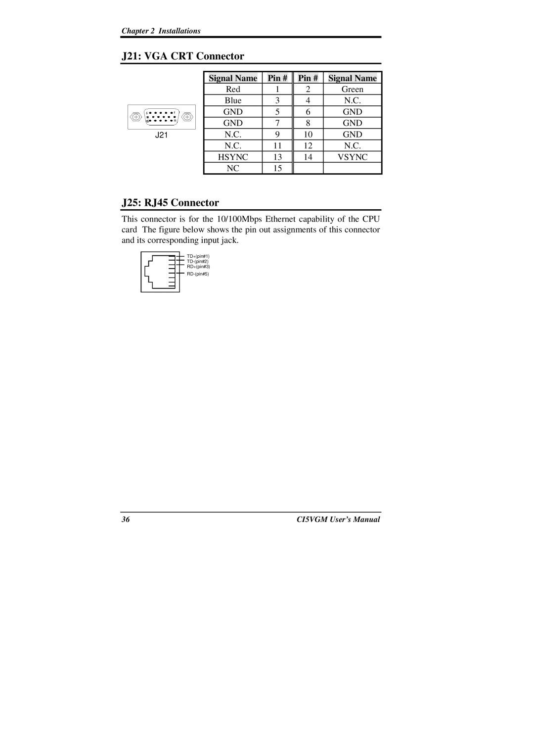
J25: RJ45 Connector
This connector is for the 10/100Mbps Ethernet capability of the CPU card The figure below shows the pin out assignments of this connector and its corresponding input jack.
TD+(pin#1)
RD+(pin#3)
36 | CI5VGM User’s Manual |