Full-Size Pentium All-in-one CPU Card
Industrial CPU Card
User’s Manual
CI5VGM Series
Copyright Notice
Acknowledgments
CI5VGM User’s Manual
Appendix
Contents
Page
DSTN LCD Panel
Settings for New Cyrix/AMD CPUs
SW3 LCD Panel Type Select
TFT LCD Panel
Introduction
Checklist
Description
1 Optional CD containing Intel LANDesk Client Manager
Secondary Cache 1 MB
Features
Specifications
Processor
Memory Sockets
DMI BIOS Support
PCI Bus Ethernet Interface Intel 82558B
Environmental and Mechanical AT Power Supply Max. 15A @+5V
Intelligence
Board Dimensions
Chapter 1 Introduction
CI5VGM User’s Manual
This page is intentionally left blank
Chapter 1 Introduction
CI5VGM User’s Manual
Connectors on the CI5VGM
Installations
CPU Installation
Memory Installation
CPU Installation
DIMM2
Memory Installation
168Pin DIMM 3.3V - SDRAM or EDO DRAM
DIMM3
DIMM1
168Pin DIMM 3.3V - SDRAM or EDO DRAM continued
DIMM3
DIMM2
Jumpers on the CI5VGM
Chapter 2 Installations
Jumper Locations on the CI5VGM
CI5VGM User’s Manual
CPU FREQ
SW11-8 CPU Frequency Selector
For Intel Pentium, IDT WinChip 2-3D / C6
Multiplier
Clock
For Cyrix 6x86, 6x86L, 6x86MX. MII CPU
CPU FREQ
Clock
For AMD K5, K6, K6-2 CPU
Multiplier
CPU FREQ
Run AGP Clock
short
Run CPU Clock
short
6x86L
WinChip 2-3D
0.35∝
P55C
Function
3.3V Setting
5V Setting
For Dual Voltage CPU Intel P55C, Cyrix 6x86L/MX/MII, AMD K6/K6-2
RS-232
Address
Address
COM2
Function
Setting
Chapter 2 Installations
Clear CMOS Content
Connectors on the CI5VGM
Connector Locations on the CI5VGM
Chapter 2 Installations
CI5VGM User’s Manual
Signal Name
Signal Name
Signal Name
Signal Name
IDE2 Secondary IDE Connector
IDE1 Primary IDE Connector
Signal Name
Signal Name
Signal Name
Signal Name
Signal Name
Signal Name
Pin #
J4 Audio I/O Connector Continued
Signal Name
Chapter 2 Installations
Pin #
Signal Name
Signal Name
Pin #
Signal Name
Speaker Pins 1
Signal Name
Power LED and Keylock Pins 11
Reset Switch Pins 9 and
ATX Power ON Switch Pins 7 and
Turbo LED Connector Pins 8 and
Pin # Signal Name
Pin #
J9 LCD Panel Connector
Signal Name
Signal Name
Signal Name
Pin # Signal Name
Pin # Signal Name
Pin # Signal Name
Pin #
Signal Name
Signal Name
Signal Name
Signal Name
J21 VGA CRT Connector
J25 RJ45 Connector
Signal Name
Disabling Watchdog
Watchdog Timer Configuration
WATCHDOG TIMER CONTROL TABLE
Enabling Watchdog
Chapter 3 BIOS Configuration
This page was intentionally left blank
CI5VGM User’s Manual
BIOS Configuration
PCI/VGA Palette Snoop
Load BIOS Defaults
BIOS Introduction
BIOS Setup
Press DEL to Enter Setup
STANDARD CMOS SETUP
Date
Standard CMOS Setup
CYLS
MODE for IDE HDD only Auto
Time
Primary HDDs / Secondary HDDs
Drive A / Drive B
Video
Halt On
BIOS Features Setup
Virus Warning
CPU Internal Cache / External Cache
Boot Up NumLock Status
Quick Power On Self Test
Boot Sequence
Boot Up Floppy Seek
Security Option
Typematic Rate Setting
Typematic Delay Msec
Typematic Rate Chars/Sec
C8000 - CBFFF Shadow/DC000 - DFFFF Shadow
Video BIOS Shadow
Sustained 3T Write
DRAM Timing
SDRAM Cycle Length
DRAM Read Pipeline
Memory Hole at 15MB - 16MB
Video BIOS Cacheable
System BIOS Cacheable
Cyrix M2 ADS# delay
USB Keyboard Support
CPU Warning Temperature
Temperature/Fan Speed/Voltage
Shutdown Temperature
Power Management Setup
Power Management
ACPI function
Video Off Option
HDD Power Down
Doze Mode
PM Control by APM
PM Events
Suspend Mode
Resources Controlled by
PNP/PCI Configuration
PNP OS Installed
Reset Configuration Data
PCI Dynamic Bursting
PCI Delay Transaction
PCI #2 Access #1 Retry
CPU to PCI Write Buffer
LOAD BIOS DEFAULTS
Load BIOS Defaults
Load Setup Defaults
Load BIOS Defaults Y/N? N
OnChip IDE First/Second Channel
IDE Prefetch Mode
IDE HDD Block Mode
Integrated Peripherals
Init AGP Display First
UART 2 Mode
Parallel Port Mode
IDE Primary/Secondary Master/Slave UDMA
Supervisor / User Password
SUPERVISOR PASSWORD
Enter Password
ESC SKIP
IDE HDD Auto Detection
EXIT WITHOUT
Chapter 3 BIOS Configuration
SAVE & EXIT SETUP
CI5VGM User’s Manual
Audio Driver Installation Guide
floppy disk that comes with your motherboard in the CD-ROM or
Installing the Audio Drivers for Windows
Step 3. When the figure below appears, press the Next to search for the driver
Step 5. The Update Device Driver Wizard will find YAMAHA OPL3-SAx Sound System and show the following figure. Click Finish
Step 7. When file copying is done and the figure below appears, insert the Windows 95 CD into the CD-ROM, and then click OK
CI5VGM User’s Manual
Chapter 4 Audio Driver Installation Guide
CI5VGM User’s Manual
Setting the 3D Function
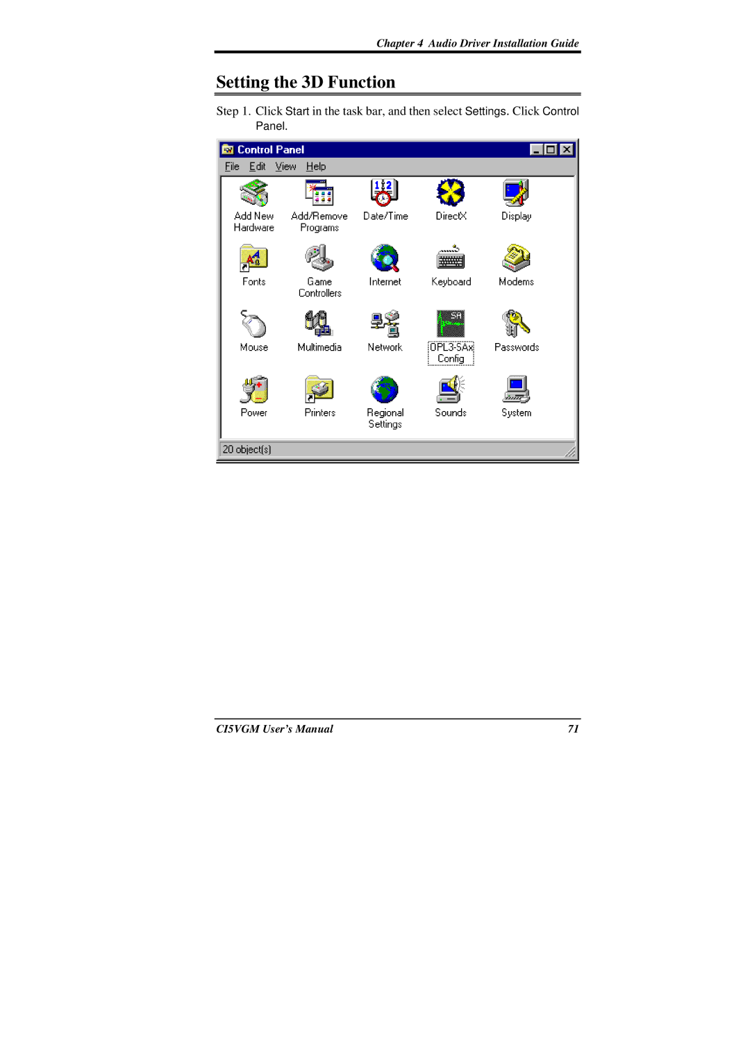
Chapter 4 Audio Driver Installation Guide
Panel
CI5VGM User’s Manual
Step 2. Double click the OPL3-SAx Config icon
Step 3. Move Ymersion slide bar to adjust the 3D effects
Chapter 4 Audio Driver Installation Guide
Using YAMAHA Software Wavetable for Windows
Chapter 4 Audio Driver Installation Guide
Step 2. In the Control Panel window, double click the Multimedia icon
CI5VGM User’s Manual
OPL3-SA SoftSynth
OPL3-SA FM Synthesizer
OPL3-SA MPU401
Select Hardware Wavetable
Installing the Audio Drivers for Windows NT
Installing Trident 9520/25 Drivers for Windows
VGA Driver Installation Guide
This chapter describe the VGA driver installation procedure for the
Installing Trident 9520/25 Drivers for Windows
Chapter 5 VGA Driver Installation Guide
CI5VGM User’s Manual
Step 2. Double click Display, then click Settings
Chapter 5 VGA Driver Installation Guide
CI5VGM User’s Manual
Chapter 5 VGA Driver Installation Guide
Step 3. Click Advanced Properties, then click Change
CI5VGM User’s Manual
Step 4. Click Have Disk .... If D is your CDROM, type D\VGA\Trid9520\WIN95 and click OK. If you are using the
CI5VGM User’s Manual
Chapter 5 VGA Driver Installation Guide
Step 6. After the files are copied, click Close
CI5VGM User’s Manual
Installing Trident 9520/25 Drivers for Windows
Chapter 5 VGA Driver Installation Guide
CI5VGM User’s Manual
Chapter 5 VGA Driver Installation Guide
Step 2. Double click Display
CI5VGM User’s Manual
Step 3. Click Settings
Chapter 5 VGA Driver Installation Guide
CI5VGM User’s Manual
Chapter 5 VGA Driver Installation Guide
Step 4. Click Advanced
CI5VGM User’s Manual
Chapter 5 VGA Driver Installation Guide
Step 5. Click Adapter
CI5VGM User’s Manual
Chapter 5 VGA Driver Installation Guide
Step 6. Click Change
CI5VGM User’s Manual
Chapter 5 VGA Driver Installation Guide
Step 7. Click Next
CI5VGM User’s Manual
Chapter 5 VGA Driver Installation Guide
Step 9. Click Have Disk
CI5VGM User’s Manual
Chapter 5 VGA Driver Installation Guide
Step 12. Click Next
CI5VGM User’s Manual
Chapter 5 VGA Driver Installation Guide
Step 13. After the files are copied, click Finish
CI5VGM User’s Manual
Chapter 5 VGA Driver Installation Guide
Step 12. Click Close
CI5VGM User’s Manual
Chapter 5 VGA Driver Installation Guide
Step 13. Click Close
CI5VGM User’s Manual
Installing Trident 9520/25 Drivers for Windows NT
System Monitor Utility
Chapter 6 System Monitor Utility
CI5VGM User’s Manual
System Monitor is a utility software that oversee the general performance of systems, covering areas like system temperature, system voltage, CPU and system fan rotational speeds. If conditions become adversed, that is, when voltages are erratic or CPU temperature exceeds the safe limits, an alarm will be sounded thereby preventing system crashing and ensuring overall stability
CI5VGM User’s Manual
The following screen appears upon clicking on the System Monitor icon
The section below describes the different functions of System Monitor
Chapter 6 System Monitor Utility
2. Power - displays the current voltage status
Chapter 6 System Monitor Utility
CI5VGM User’s Manual
3. Memory - displays the current memory usage status
Chapter 6 System Monitor Utility
CI5VGM User’s Manual
5. Disk - displays the disk supported formats and disk space
Chapter 6 System Monitor Utility
CI5VGM User’s Manual
6. Heat - displays the CPU and system temperatures
Chapter 6 System Monitor Utility
CI5VGM User’s Manual
the acceptable voltage range between the MAX
12 Volts - 10% 10.8V ~ 5 Volts - 5% 4.75 ~ 5.25%
Vio - 5% Vio for P54C CPU is 3.5V. Vio for P55C is 3.3V. Vcore- 5%
Chapter 6 System Monitor Utility
LANDesk Client Manager
Introduction
NOTE During Setup, you will be asked to install Internet Explorer
Installation
Installing the Local Version of LDCM
Choose the directory location where Setup will install LANDesk Client Manager. Click “Browse” if you want to change the directory suggested. Otherwise, click “Next” to start installing LDCM
Installing the Administrative Version of LDCM
CI5VGM User’s Manual
Chapter 7 LANDesk Client Manager
This page is intentionally left blank
Chapter 7 LANDesk Client Manager
CI5VGM User’s Manual
Ethernet Setup User’s Guide
Introduction
Software Drivers Support
Features
Requires ATX power supply with 5VSB, 720mA
1. Click Start ⇒ Select Settings ⇒ Select Control Panel
LAN Driver Installation for Windows
CI5VGM User’s Manual
Chapter 8 Ethernet Setup User’s Guide
2. Click System
3. Click Device Manager
CI5VGM User’s Manual
Chapter 8 Ethernet Setup User’s Guide
4. Expand Other Devices
5. Select PCI Ethernet Controller, then click Properties
Chapter 8 Ethernet Setup User’s Guide
6. Click Driver
CI5VGM User’s Manual
7. Click Update Driver
Chapter 8 Ethernet Setup User’s Guide
CI5VGM User’s Manual
8. Insert the diskette labeled Intel 82558B LAN Windows 95/98 & Windows NT 4.0 Drivers into the floppy disk drive, then click Next
Chapter 8 Ethernet Setup User’s Guide
10. Click OK 11. Type A\, then click OK 12. Click OK
CI5VGM User’s Manual
Chapter 8 Ethernet Setup User’s Guide
13. Type the Computer Name and Workgroup, then click Close
14. Insert the Windows 95 CD ROM, then click OK
15. Type D\Win95 Assuming D\Win95 is the directory location of the Windows 95 files, then click OK
LAN Driver Installation for Windows NT
Running Diagnostics
CI5VGM User’s Manual
4. Selecting Install network drivers will show the following screen
Chapter 8 Ethernet Setup User’s Guide
3. Selecting Test adapter will show the following screen
CI5VGM User’s Manual
Chapter 8 Ethernet Setup User’s Guide
CI5VGM User’s Manual
Appendix
A. I/O Port Address Map B. Interrupt Request Lines IRQ
Appendix
A. I/O Port Address Map
Address
Device Description
B. Interrupt Request Lines IRQ
Level
Function