Chapter 2 Installations
J8: Front Bezel Connector
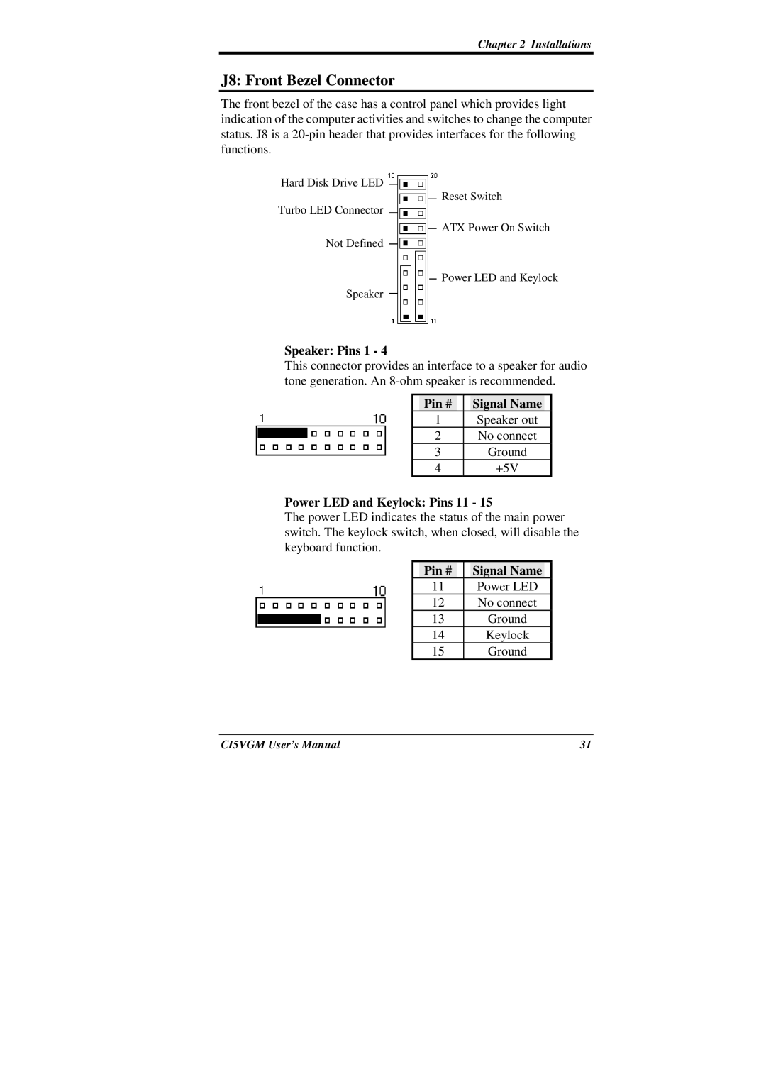
The front bezel of the case has a control panel which provides light indication of the computer activities and switches to change the computer status. J8 is a
Hard Disk Drive LED
Reset Switch
Turbo LED Connector
ATX Power On Switch
Not Defined
Power LED and Keylock
Speaker
Speaker: Pins 1 - 4
This connector provides an interface to a speaker for audio tone generation. An
| Pin # |
|
| Signal Name |
|
| 1 |
|
| Speaker out |
|
| 2 |
|
| No connect |
|
| 3 |
|
| Ground |
|
| 4 |
|
| +5V |
|
Power LED and Keylock: Pins 11 - 15
The power LED indicates the status of the main power switch. The keylock switch, when closed, will disable the keyboard function.
| Pin # |
|
| Signal Name |
|
| 11 |
|
| Power LED |
|
| 12 |
|
| No connect |
|
| 13 |
|
| Ground |
|
| 14 |
|
| Keylock |
|
| 15 |
|
| Ground |
|
CI5VGM User’s Manual | 31 |