■Installation
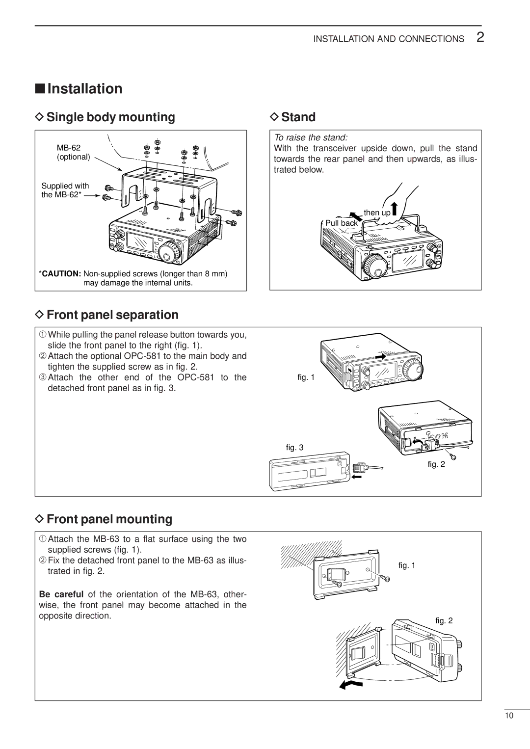
DSingle body mounting
Supplied with ![]()
![]()
![]() the
the ![]()
![]()
![]()
*CAUTION:
INSTALLATION AND CONNECTIONS 2
DStand
To raise the stand:
With the transceiver upside down, pull the stand towards the rear panel and then upwards, as illus- trated below.
then up![]()
Pull back
DFront panel separation
➀While pulling the panel release button towards you, slide the front panel to the right (fig. 1).
➁Attach the optional
➂Attach the other end of the
fig. 3
fig. 2
DFront panel mounting
➀Attach the
➁Fix the detached front panel to the
Be careful of the orientation of the
fig. 1
fig. 2
10