OPTIONAL INSTALLATIONS/SETTINGS 10
■CR-282 HIGH-STABILITY CRYSTAL UNIT
By installing the
➀Remove the bottom cover as shown on the oppo- site page.
➁Remove the 5 screws and 2 flat cables holding the PLL unit in place.
➂Remove the existing crystal unit.
➃Put the
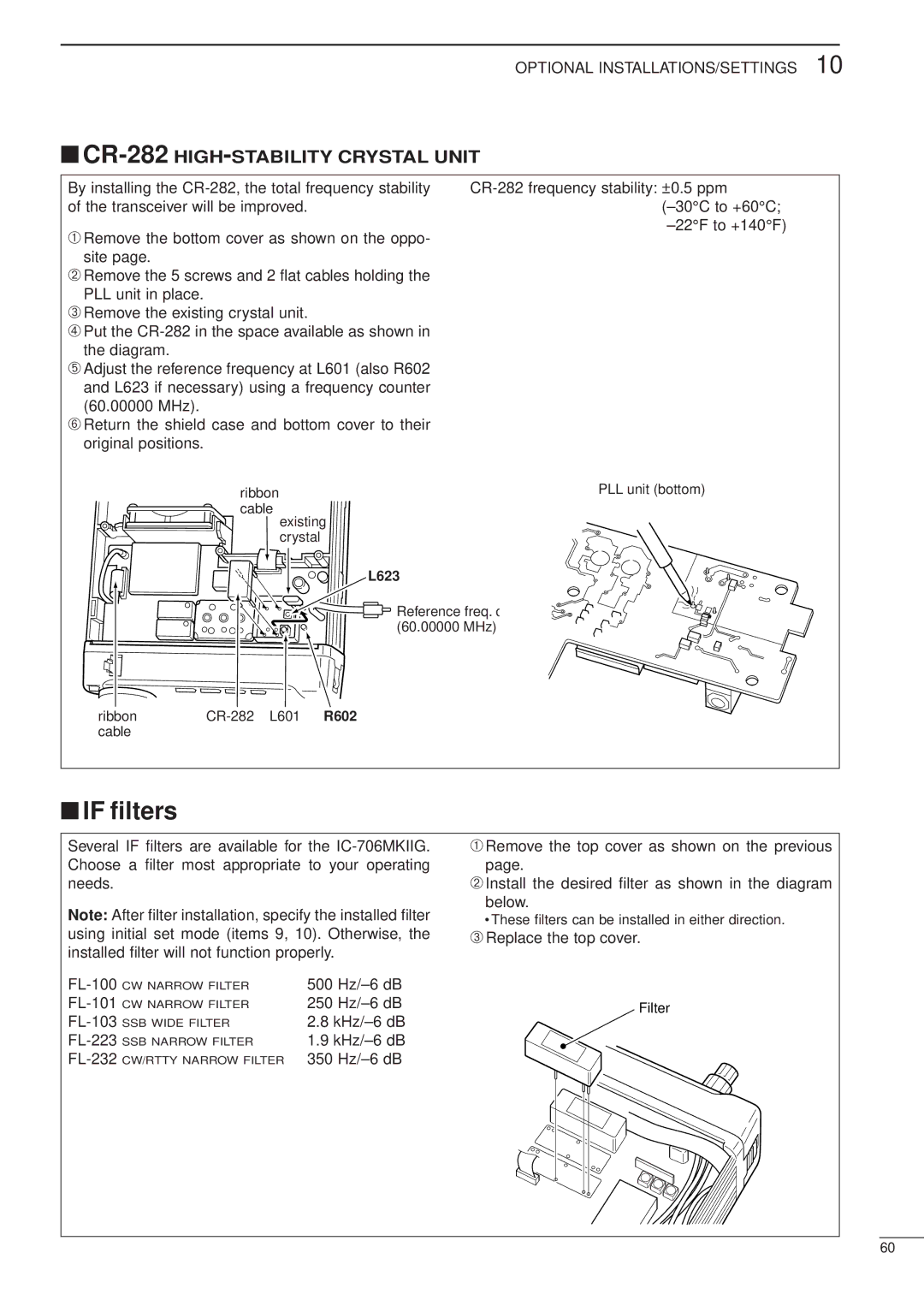
➄Adjust the reference frequency at L601 (also R602 and L623 if necessary) using a frequency counter (60.00000 MHz).
➅Return the shield case and bottom cover to their original positions.
ribbon | PLL unit (bottom) |
cable |
|
existing crystal
L623
![]() Reference freq. c (60.00000 MHz)
Reference freq. c (60.00000 MHz)
ribbon | |
cable |
|
■IF filters
Several IF filters are available for the
Note: After filter installation, specify the installed filter using initial set mode (items 9, 10). Otherwise, the installed filter will not function properly.
500 | ||
CW NARROW FILTER | 250 | |
SSB WIDE FILTER | 2.8 | |
SSB NARROW FILTER | 1.9 | |
CW/RTTY NARROW FILTER | 350 | |
➀Remove the top cover as shown on the previous page.
➁Install the desired filter as shown in the diagram
below.
•These filters can be installed in either direction.
➂Replace the top cover.
Filter
60