3 FREQUENCY SETTING
■When first applying power (CPU resetting)
Before first applying power, make sure all connections required for your system are complete by referring to section 2. Then, reset the transceiver using the follow- ing procedure.
Note: Resetting clears all programmed contents in memory channels and returns all initial set mode and quick set mode contents to their default values.
[POWER]
USB
[Y]
[Z]
The transceiver displays
➀Make sure the transceiver power is OFF.
➁While pushing [Y] and [Z], push [POWER] to turn power ON.
•The internal CPU is reset.
•The transceiver displays as shown at right when reset- ting is complete.
DM1 display selection
If you can’t figure out how to return to the M1 display: While pushing [MENU], turn power ON.
S1 3 | 5 7 9 20 40 | 60dB | VFO A | BLANK |
| ||||
PO | 5 | 10 |
| CH |
M1 | SPL | A/B A=B | ||
its initial frequency and mode.
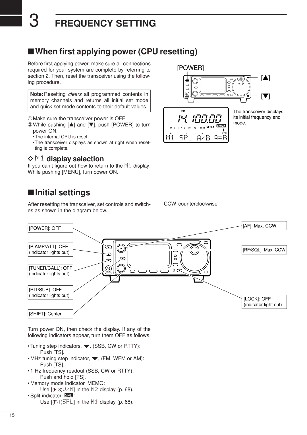
■Initial settings
After resetting the transceiver, set controls and switch- | CCW: counterclockwise |
es as shown in the diagram below. |
|
[POWER]: OFF
[P.AMP/ATT]: OFF (indicator lights out)
[TUNER/CALL]: OFF ![]() (indicator lights out)
(indicator lights out)
[RIT/SUB]: OFF (indicator lights out)
[SHIFT]: Center
Turn power ON, then check the display. If any of the following indicators appear, turn them OFF as follows:
•Tuning step indicators, Z, (SSB, CW or RTTY): Push [TS].
•MHz tuning step indicator, Z, (FM, WFM or AM): Push [TS].
•1 Hz frequency readout (SSB, CW or RTTY): Push and hold [TS].
•Memory mode indicator, MEMO:
Use
• Split indicator, ä:
Use
[AF]: Max. CCW
[RF/SQL]: Max. CCW
[LOCK]: OFF (indicator light out)
15