■SWR
The
RECEIVE AND TRANSMIT 4
☞NOTE: The SWR of ANT1 only can be read since ANT2 has no measuring circuit.
DMeasuring SWR
The
(A) Spot measurement; or (B) Plot measurement.
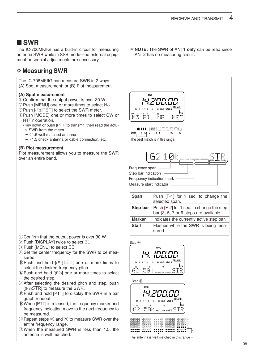
(A) Spot measurement
➀Confirm that the output power is over 30 W.
➁Push [MENU] one or more times to select M3.
➂Push [(F3)MET] to select the SWR meter.
➃Push [MODE] one or more times to select CW or RTTY operation.
•Key down or push [PTT] to transmit; then read the actu- al SWR from the meter:
➠≤ 1.5 well matched antenna
➠> 1.5 check antenna or cable connection, etc.
CW
|
|
|
|
|
|
| BLANK |
S1 | 3 | 5 | 7 9 | 20 | 40 | 60dB | VFO A |
SWR | 1 | 1.5 2 | 3 |
| ∞ |
| CH |
M3 FIL | NB | MET | |||||
SWR |
| 1 | 1.5 | 2 | 3 | 5 | ∞ 10 |
The best match is in this range.
(B) Plot measurement
Plot measurement allows you to measure the SWR over an entire band.
G2 10k | STR |
Frequency span |
|
Step bar indication |
|
Frequency indication mark |
|
Measure start indicator |
|
qConfirm that the output power is over 30 W. wPush [DISPLAY] twice to select G1.
ePush [MENU] to select G2.
rSet the center frequency for the SWR to be mea-
sured.
tPush and hold [(F1)10k] one or more times to select the desired frequency pitch.
yPush and hold [(F2)] one or more times to select the desired step.
uAfter selecting the desired pitch and step, push [(F3)STR] to measure the SWR.
iPush and hold [PTT] to display the SWR in a bar graph readout.
oWhen [PTT] is released, the frequency marker and frequency indication move to the next frequency to be measured.
!0Repeat steps i.and o to measure SWR over the entire frequency range.
!1When the measured SWR is less than 1.5, the antenna is well matched.
Span |
| Push | |||
|
| selected span. | |||
Step bar | Push | ||||
|
| bar (3, 5, 7 or 9 steps are available. | |||
|
| ||||
Marker | Indicates the currently active step bar. | ||||
|
|
| |||
Start |
| Flashes while the SWR is being mea- | |||
|
| sured. |
| ||
|
|
|
|
|
|
Step y |
|
|
|
|
|
|
|
| RTTY |
| |
|
|
|
|
| BLANK |
S1 3 5 | 7 9 | 20 | 40 | 60dB | VFO A |
PO | 5 |
|
| 10 | CH |
G2 50k |
|
| STR | ||
Step o |
|
|
|
|
|
| USB |
|
|
|
|
|
|
|
|
| BLANK |
S1 3 5 | 7 9 | 20 | 40 | 60dB | VFO A |
PO | 5 |
|
| 10 | CH |
G2 50k |
|
| STR | ||
4.0
3.5
3.0
2.5
2.0
1.�5
1.0
The antenna is well matched in this range
38