RECEIVE AND TRANSMIT 4
DRF gain and squelch
The
The RF (Radio Frequency) gain is used to adjust the receiver gain.
• This control should be set to the 11 o’clock position for |
normal use. |
• [RF/SQL] control priority
Initial set mode | USB, LSB, | AM, FM, WFM | |
setting | CW, RTTY | ||
| |||
SQL*1 | SQL | SQL | |
AUTO | RF GAIN | SQL | |
|
|
| |
RF • SQL*2 | RF/SQL | RF/SQL | |
|
|
|
*1Default; *2Default for USA version.
• Shallow rotation moves the |
the signal strength which can be received. |
The SQUELCH removes noise output from the speaker (closed condition) when no signal is received. The squelch is particularly effective for FM. It is also available for the other modes.
Note: The recommended position for RF gain is the 11 o’clock position since this sets RF gain to the max.
When set to AUTO, SQL is active in FM/WFM/AM; RF is active in SSB/CW/RTTY.
Max. RF gain position
AF![]()
![]() RF/SQL
RF/SQL
RF gain | Same effect as at |
decreases | the center position |
•When operating in FM, first rotate the control fully coun- terclockwise. Then, rotate the control clockwise to the point where the noise just disappears. This is the best position. The squelch does not open for weak signals when it is set too deep.
•A segment appears in the
Noise squelch | ||
threshold point | ||
threshold point | ||
| ||
AF | RF/SQL | |
Squelch | Deep | |
opens |
|
DSimple band scope
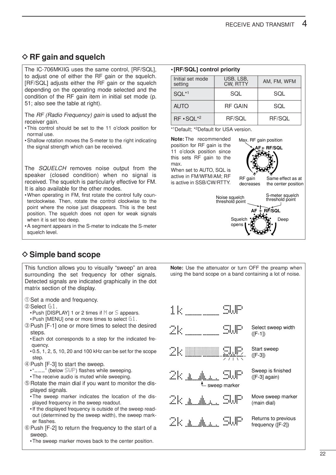
This function allows you to visually “sweep” an area surrounding the set frequency for other signals. Detected signals are indicated graphically in the dot matrix section of the display.
➀Set a mode and frequency.
➁Select G1.
•Push [DISPLAY] 1 or 2 times if M or S appears.
•Push [MENU] one or more times to select G1.
➂Push [F-1] one or more times to select the desired steps.
•Each dot corresponds to a step for the indicated fre- quency.
•0.5, 1, 2, 5, 10, 20 and 100 kHz can be set for the scope step.
➃Push
•“___” (below SWP) flashes while sweeping.
•The receive audio is muted while sweeping.
➄Rotate the main dial if you want to monitor the dis- played signals.
•The sweep marker indicates the location of the dis- played frequency in the sweep readout.
•If the displayed frequency is outside of the sweep read- out (determined by the sweep width), the sweep mark- er flashes.
➅Push
•The sweep marker moves back to the center position.
Note: Use the attenuator or turn OFF the preamp when using the band scope on a band containing a lot of noise.
1k |
|
| SWP |
|
2k |
|
| SWP | |
|
|
|
| Select sweep width |
2k |
|
| SWP | |
|
|
|
| Start sweep |
2k |
|
| SWP | Sweep is finished |
|
| |||
2k |
|
| sweep marker |
|
|
| |||
|
|
| ||
|
| SWP | (main dial) | |
|
|
|
| Move sweep marker |
2k |
|
| SWP | Returns to previous |
|
| frequency |
22