Installation 2-5
Cart Assembly
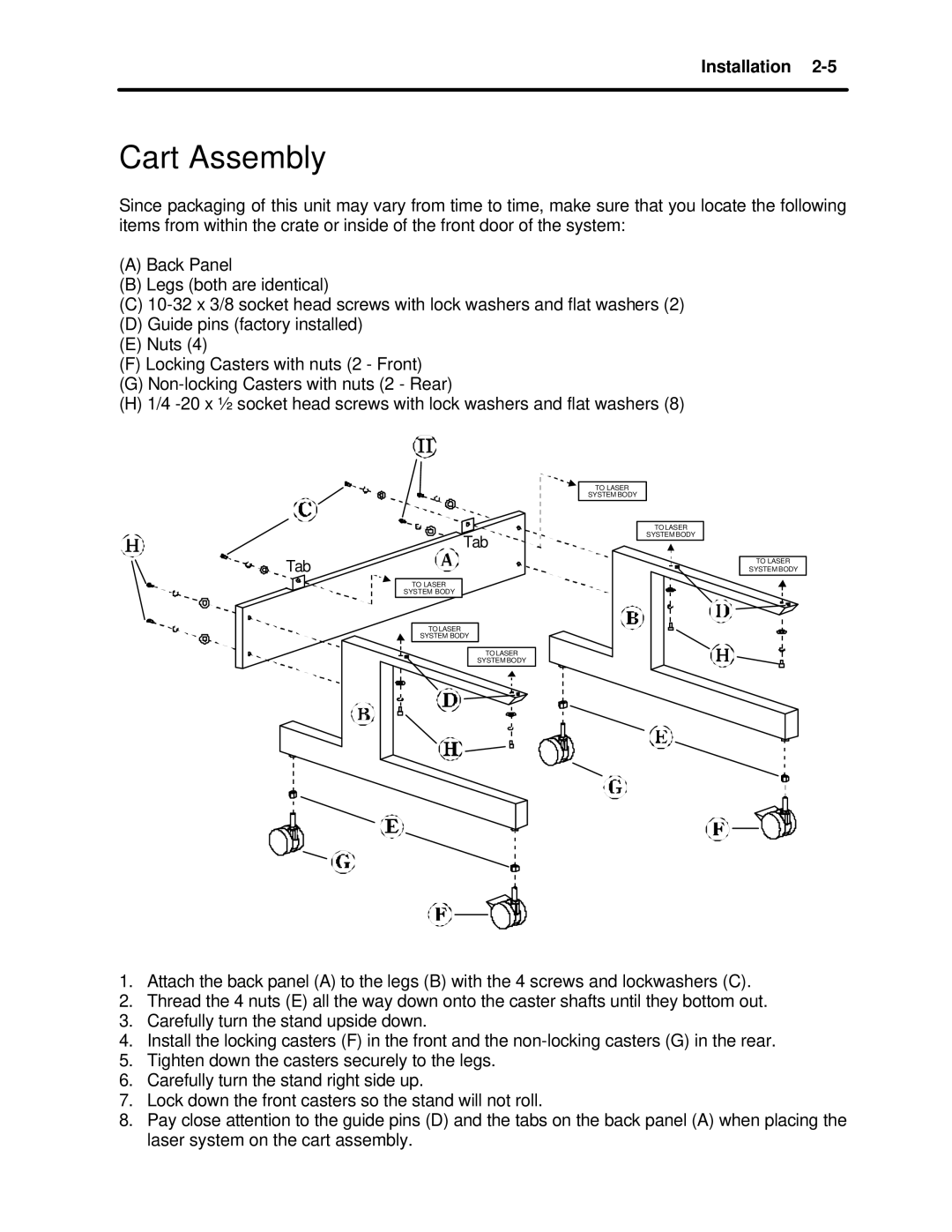
Since packaging of this unit may vary from time to time, make sure that you locate the following items from within the crate or inside of the front door of the system:
(A)Back Panel
(B)Legs (both are identical)
(C)
(D)Guide pins (factory installed)
(E)Nuts (4)
(F)Locking Casters with nuts (2 - Front)
(G)
(H)1/4
TO LASER
SYSTEM BODY
Tab
Tab
TO LASER
SYSTEM BODY
TO LASER
SYSTEM BODY
TO LASER
SYSTEM BODY
TO LASER
SYSTEM BODY
TO LASER
SYSTEM BODY
1.Attach the back panel (A) to the legs (B) with the 4 screws and lockwashers (C).
2.Thread the 4 nuts (E) all the way down onto the caster shafts until they bottom out.
3.Carefully turn the stand upside down.
4.Install the locking casters (F) in the front and the
5.Tighten down the casters securely to the legs.
6.Carefully turn the stand right side up.
7.Lock down the front casters so the stand will not roll.
8.Pay close attention to the guide pins (D) and the tabs on the back panel (A) when placing the laser system on the cart assembly.