DTR-9.1
Avis
Important Safeguards
For U.S. model
Precautions
For Canadian model
Modele pour les Canadien
Contents
Contents
Supplied accessories
Features
Assignable and Configuaragble 12-Volt Trig
THX Ultra
Using the remote controller
Before using remote controller
Front panel
Front panel facilities
Front panel door
Front panel display
Front panel facilities
Preset
Tuning
FM Mode
Off
SEND/LEARN indicator LCD display Power ON/STNBY button
Remote controller
Model NO. DTR-9.1
Rear panel facilities
Coaxial, optical, and input-only AC-3RF
Rear panel facilities
AC Inlet
Video IN/OUT
Video Monitor OUT
Example of how to connect your equipment
Example of how to connect your equipment
Default setting
Standard connections
Connecting a turntable
Connecting your audio components
Connecting an MD recorder, DAT deck, or CD recorder
Connecting a compact disc player
Connecting a video cassette recorder
Connecting a LD player
Connecting a satellite tuner or television
Connecting a television monitor or projector
Ideal speaker configuration
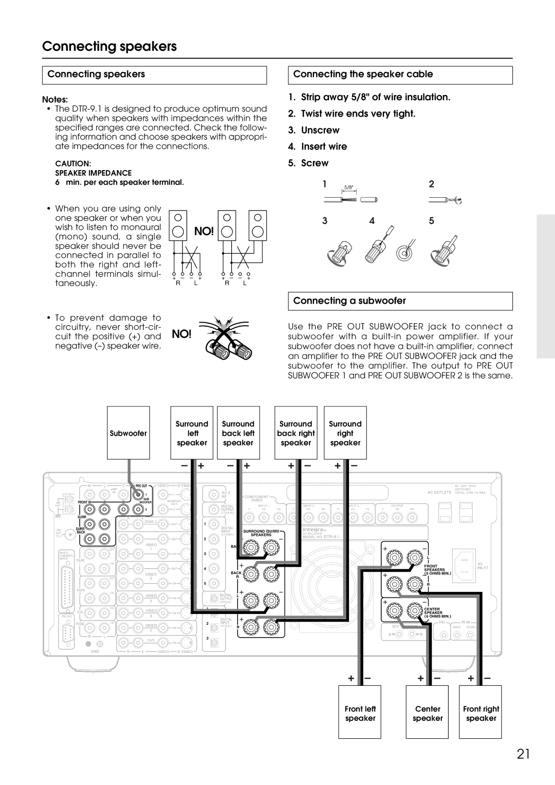
Connecting speakers
Minimum speaker configuration for surround sound playback
Speaker placement
Connecting a subwoofer
Connecting speakers
Connecting antennas
Connecting the AM loop antenna
Assembling the AM loop antenna
Connecting an FM outdoor antenna
Connecting antennas
Connecting an AM outdoor antenna
Directional linkage
Connecting to the IR in Zone 2 input
Connecting the main and remote zones
Outline
Cabinet
Connecting to the IR in Main input
Connecting a graphic equalizer Connecting power amplifiers
Remove the jumper plugs Connect the power amplifiers
Remove the jumper plugs Connect a graphic equalizer
Turning the power on from the remote controller
Connecting the power
On-Screen Display OSD menu
Up into six menus Speaker Setup, Input Setup, Listening
Your home theater, and it rarely needs to be Changed later
OSD menu consists of a main screen that is divided
On-Screen Display OSD menu
Navigating through the OSD menu
Press the Menu button
Speaker Config sub-menu
Speaker Setup
Speaker Distance sub-menu
Speaker Setup
Calibrating the speaker levels
Level Calibration sub-menu
Bass Peak Level Bass Peak Level Manager* sub-menu
LFE Level Setup sub-menu
Digital Setup sub-menu
Input Setup
Input Setup
Video Setup sub-menu
Multichannel Setup sub-menu
DTS Mpeg
Listening Mode Preset sub-menu
Listening Modes
Input source signals
Input Setup
123456789012345678901234 4.Preference
Delay sub-menu Sound Effect sub-menu
Character Input sub-menu
Miscellaneous Setup
Listening Mode Setup menu
Listening Mode Setup
Listening Mode Setup
Description listening mode parameters
THX
Preference
Volume Setup sub-menu
OSD Setup sub-menu
Preference
OSD Tweak
Lock Setup sub-menu
Zone2 OSD Setup
About
Version
Enjoying music or videos in the remote zone
Power VOL
Press the Zone 2 button on the DTR-9.1 Select a source
Input selector buttons
Preset
Listening to Radio Broadcasts
Listening to FM/AM Radio Stations
This erases the selected preset station
Press the Enter button again to finalize the procedure
Listening to Radio Broadcasts
Press the Memory button on the front panel
Selecting an input source Listening with headphones
Changing the listening mode
Adjusting the volume
Using the many features of the DTR-9.1
Enjoying music or videos with the DTR-9.1
If one of the messages shown below appears
Enjoying the multichannel output
Recording a source
Press the Rec Out button twice within 8 seconds
Start recording at the recording component as desired
Recording a source
Using the remote controller to control each device
Using remote controller
Press the AUDIO/TAPE Mode button
Controlling the DTR-9.1
Listening mode buttons
Using remote controller
Press the MD Mode button
Press the CD Mode button
Controlling an Integra CD player
Controlling an Integra MD recorder
Press the TUN input selector button
Controlling an Integra cassette tape deck
Press the DVD Mode button
SAT, CABLE, VCR, and TV Mode buttons
Controlling an Integra DVD player
Buttons
Programming procedure
Page
Press and release the same Mode button again
Erasing the programmed command from one button
SEND/LEARN indicator Mode buttons
You can only erase memorized commands and not preset ones
Press the Mode Macro button to complete the programming
Using a Macro function
Programming a Macro function
Running a Macro function
Press the Direct Macro button to complete the procedure
Using a Macro function
Programming the Direct Macro function
Check to see if the macro has been properly programmed
Press the Direct Macro button again
Press the Mode Macro button again
Macro mode programming memo
Erasing all commands and macros that have been programmed
Press the ENT button
Operation
Troubleshooting guide
Troubleshooting guide
Cannot change OSD Menu settings
OSD menu settings cannot be changed
Late Night function cannot be used
LFE Level function cannot be used
Speaker Setup
Default settings
Input Setup
Zone2 OSD Setup
Inputs
Your system setting
Tape
Your system setting
Speakers
OSD Setup
Mode
Remote controller
Specifications
Other upgraded function
Upgraded-2
Important points regarding speaker placement
Speaker configuration and placement/ Connecting speakers
Crossover80HzTHX QuitOSD
Boundary Gain
Channel digital surround format
Digital Setup sub-menu Listening Mode Preset sub-menu
Relationship between input source and listening mode
Upgraded-8
THX
When Upsampling is set to On, DTS Neo6 cannot be selected
DTS-ES
Upgraded-12
DTS-ES
Upgraded-14
Parameter
Delay sub-menu
Other upgraded function