Jumpers and connectors
Connectors on the board link it to external devices such as hard disk drives, a keyboard, or floppy drives. In addition, the board has a number of jumpers that allow you to configure your system to suit your application.
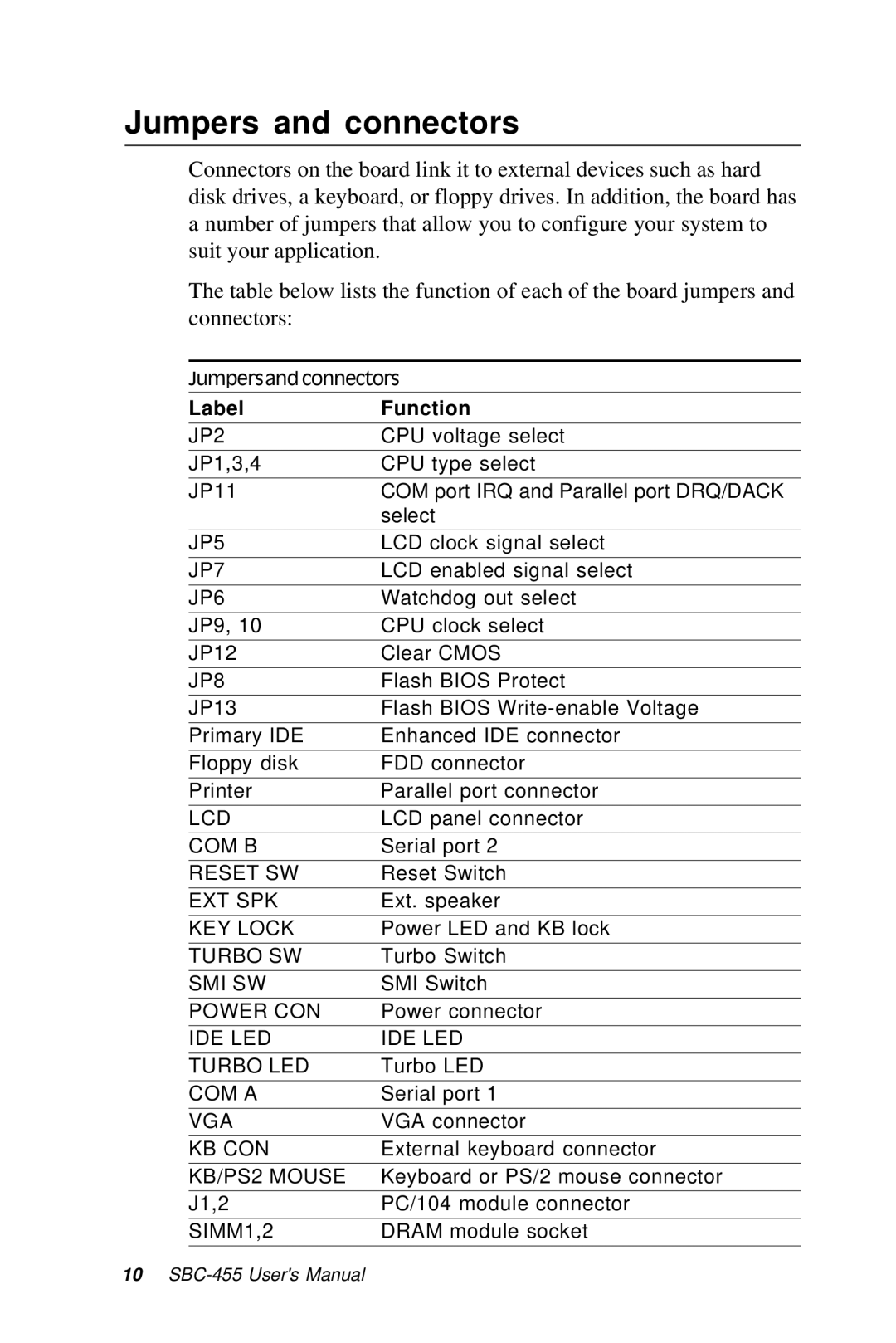
The table below lists the function of each of the board jumpers and connectors:
Jumpers and connectors
Label | Function |
JP2 | CPU voltage select |
|
|
JP1,3,4 | CPU type select |
|
|
JP11 | COM port IRQ and Parallel port DRQ/DACK |
| select |
|
|
JP5 | LCD clock signal select |
|
|
JP7 | LCD enabled signal select |
|
|
JP6 | Watchdog out select |
JP9, 10 | CPU clock select |
|
|
JP12 | Clear CMOS |
|
|
JP8 | Flash BIOS Protect |
|
|
JP13 | Flash BIOS |
Primary IDE | Enhanced IDE connector |
|
|
Floppy disk | FDD connector |
|
|
Printer | Parallel port connector |
|
|
LCD | LCD panel connector |
COM B | Serial port 2 |
|
|
RESET SW | Reset Switch |
|
|
EXT SPK | Ext. speaker |
|
|
KEY LOCK | Power LED and KB lock |
|
|
TURBO SW | Turbo Switch |
|
|
SMI SW | SMI Switch |
|
|
POWER CON | Power connector |
IDE LED | IDE LED |
|
|
TURBO LED | Turbo LED |
|
|
COM A | Serial port 1 |
|
|
VGA | VGA connector |
KB CON | External keyboard connector |
|
|
KB/PS2 MOUSE | Keyboard or PS/2 mouse connector |
|
|
J1,2 | PC/104 module connector |
|
|
SIMM1,2 | DRAM module socket |
10
