Pin assignments
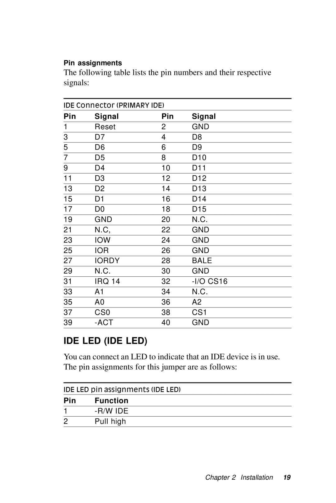
The following table lists the pin numbers and their respective signals:
IDE Connector (PRIMARY IDE)
Pin | Signal | Pin | Signal |
1 | Reset | 2 | GND |
|
|
|
|
3 | D7 | 4 | D8 |
|
|
|
|
5 | D6 | 6 | D9 |
7 | D5 | 8 | D10 |
|
|
|
|
9 | D4 | 10 | D11 |
|
|
|
|
11 | D3 | 12 | D12 |
|
|
|
|
13 | D2 | 14 | D13 |
|
|
|
|
15 | D1 | 16 | D14 |
|
|
|
|
17 | D0 | 18 | D15 |
|
|
|
|
19 | GND | 20 | N.C. |
21 | N.C, | 22 | GND |
|
|
|
|
23 | IOW | 24 | GND |
|
|
|
|
25 | IOR | 26 | GND |
|
|
|
|
27 | IORDY | 28 | BALE |
29 | N.C. | 30 | GND |
|
|
|
|
31 | IRQ 14 | 32 | |
|
|
|
|
33 | A1 | 34 | N.C. |
|
|
|
|
35 | A0 | 36 | A2 |
37 | CS0 | 38 | CS1 |
|
|
|
|
39 | 40 | GND | |
|
|
|
|
IDE LED (IDE LED)
You can connect an LED to indicate that an IDE device is in use. The pin assignments for this jumper are as follows:
IDE LED pin assignments (IDE LED)
Pin Function
1
2Pull high
Chapter 2 Installation 19
