Component Identification
Internal Components
A
B ![]()
![]()
C ![]()
![]()
![]()
![]() H
H ![]()
![]()
![]()
![]() I
I
D
E![]()
![]()
![]()
![]()
![]()
![]()
![]()
![]()
![]()
![]()
![]()
![]()
![]()
![]() J
J![]()
![]()
![]()
![]()
![]()
![]()
![]()
![]()
![]()
![]()
![]()
![]()
![]()
![]() K
K![]()
![]()
![]()
![]()
![]()
F
G
![]()
![]()
![]()
![]()
![]()
![]()
![]()
![]()
![]()
![]()
![]() L
L![]()
![]()
![]()
![]()
![]()
AF000511
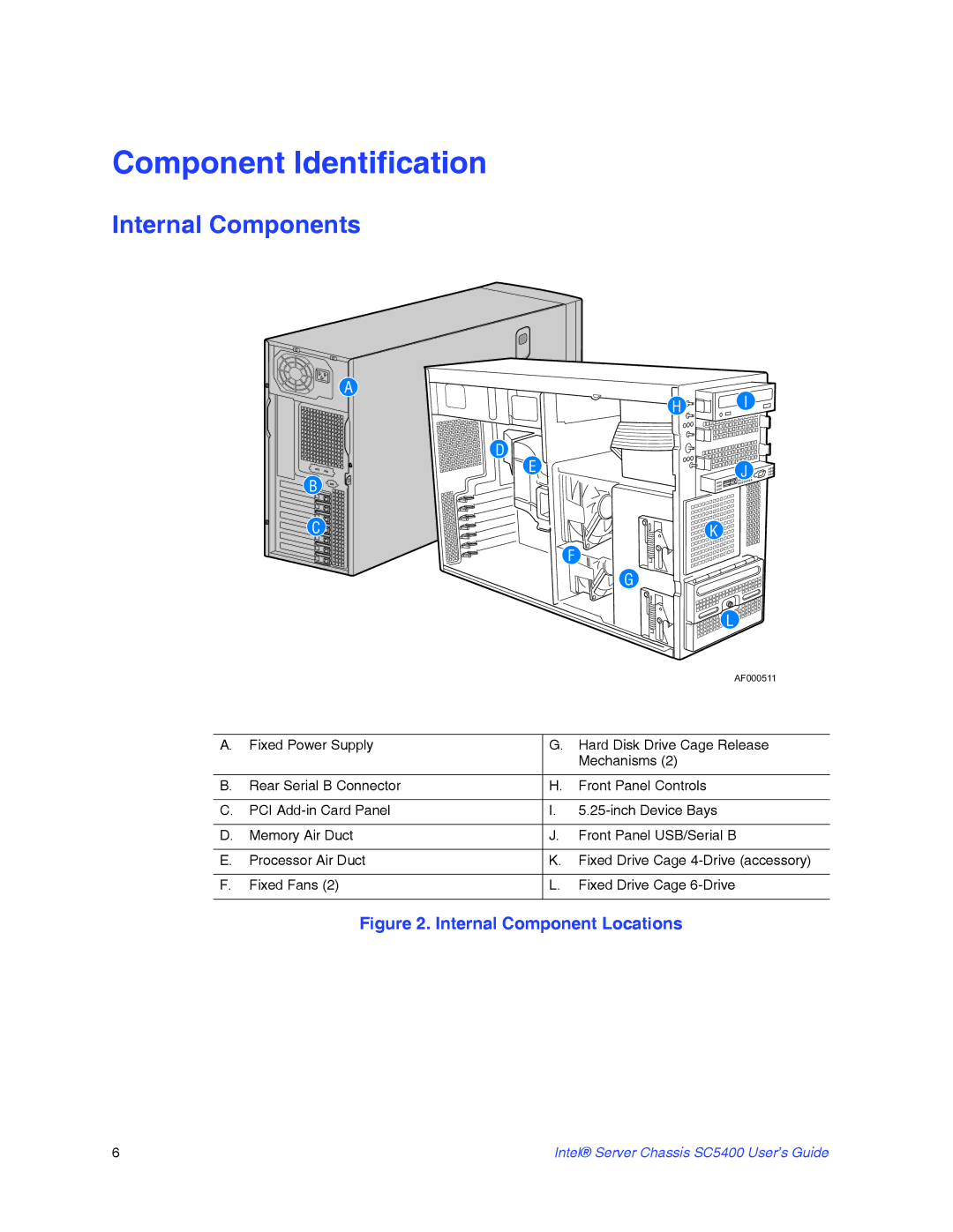
A. | Fixed Power Supply | G. | Hard Disk Drive Cage Release |
|
|
| Mechanisms (2) |
|
|
| |
B. Rear Serial B Connector | H. | Front Panel Controls | |
|
|
|
|
C. | PCI | I. | |
|
|
|
|
D. | Memory Air Duct | J. | Front Panel USB/Serial B |
|
|
| |
E. | Processor Air Duct | K. Fixed Drive Cage | |
|
|
|
|
F. | Fixed Fans (2) | L. | Fixed Drive Cage |
|
|
|
|
Figure 2. Internal Component Locations
6 | Intel® Server Chassis SC5400 User’s Guide |