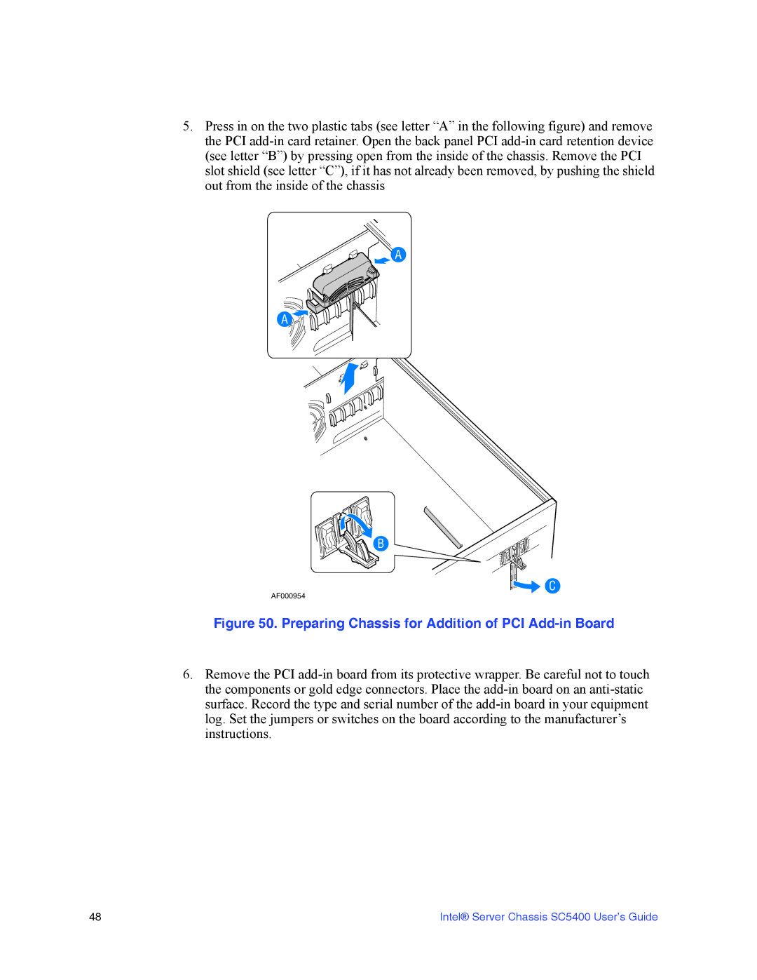
5.Press in on the two plastic tabs (see letter “A” in the following figure) and remove the PCI add-in card retainer. Open the back panel PCI add-in card retention device (see letter “B”) by pressing open from the inside of the chassis. Remove the PCI slot shield (see letter “C”), if it has not already been removed, by pushing the shield out from the inside of the chassis

A

A

B

C

AF000954

Figure 50. Preparing Chassis for Addition of PCI Add-in Board

6.Remove the PCI add-in board from its protective wrapper. Be careful not to touch the components or gold edge connectors. Place the add-in board on an anti-static surface. Record the type and serial number of the add-in board in your equipment log. Set the jumpers or switches on the board according to the manufacturer’s instructions.

48

Intel® Server Chassis SC5400 User’s Guide

Page 66
Image 66
Intel SC5400 manual Preparing Chassis for Addition of PCI Add-in Board