AF000591
Figure 47. Securing Hard Drive to Drive Carrier
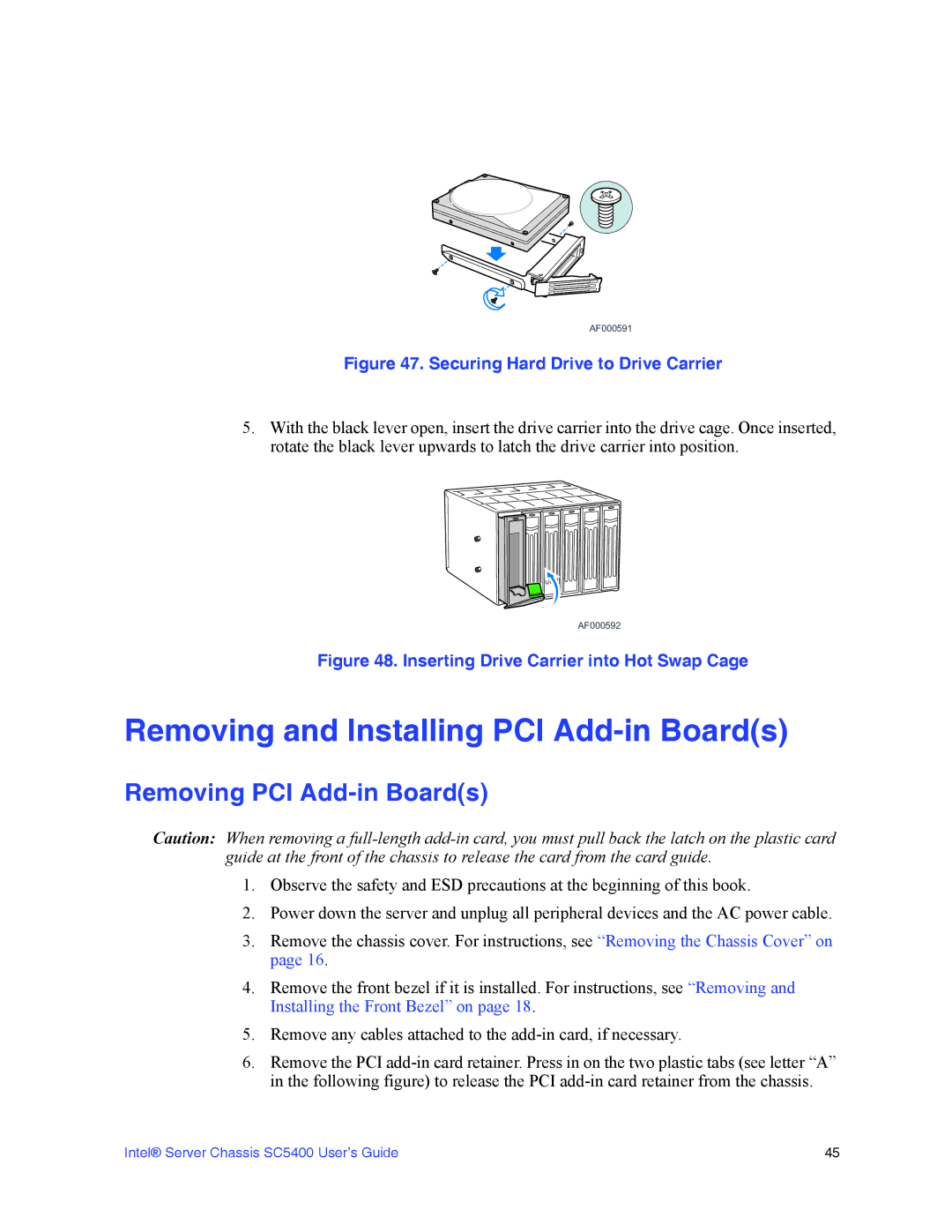
5.With the black lever open, insert the drive carrier into the drive cage. Once inserted, rotate the black lever upwards to latch the drive carrier into position.
AF000592
Figure 48. Inserting Drive Carrier into Hot Swap Cage
Removing and Installing PCI Add-in Board(s)
Removing PCI Add-in Board(s)
Caution: When removing a
1.Observe the safety and ESD precautions at the beginning of this book.
2.Power down the server and unplug all peripheral devices and the AC power cable.
3.Remove the chassis cover. For instructions, see “Removing the Chassis Cover” on page 16.
4.Remove the front bezel if it is installed. For instructions, see “Removing and Installing the Front Bezel” on page 18.
5.Remove any cables attached to the
6.Remove the PCI
Intel® Server Chassis SC5400 User’s Guide | 45 |