Intel Server Board SE7501CW2 Installation and Integration Guide
Installing Chassis Standoffs
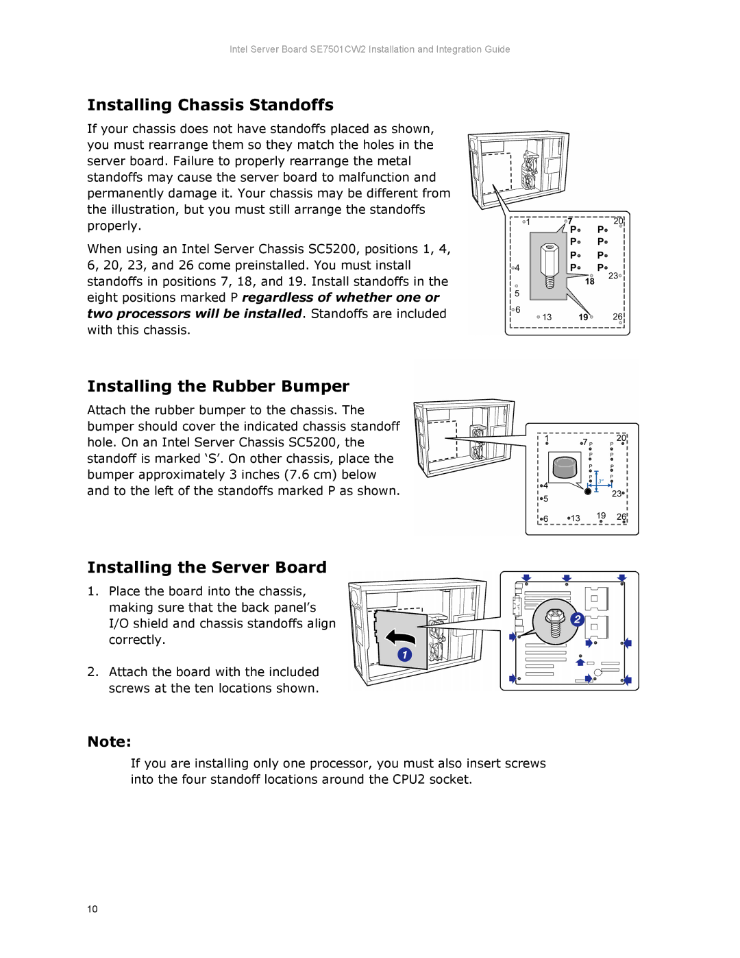
If your chassis does not have standoffs placed as shown, you must rearrange them so they match the holes in the server board. Failure to properly rearrange the metal standoffs may cause the server board to malfunction and permanently damage it. Your chassis may be different from the illustration, but you must still arrange the standoffs properly.
When using an Intel Server Chassis SC5200, positions 1, 4, 6, 20, 23, and 26 come preinstalled. You must install standoffs in positions 7, 18, and 19. Install standoffs in the eight positions marked P regardless of whether one or two processors will be installed. Standoffs are included with this chassis.
Installing the Rubber Bumper
Attach the rubber bumper to the chassis. The bumper should cover the indicated chassis standoff hole. On an Intel Server Chassis SC5200, the standoff is marked ‘S’. On other chassis, place the bumper approximately 3 inches (7.6 cm) below and to the left of the standoffs marked P as shown.
Installing the Server Board
1.Place the board into the chassis, making sure that the back panel’s I/O shield and chassis standoffs align correctly.
2.Attach the board with the included screws at the ten locations shown.
Note:
If you are installing only one processor, you must also insert screws into the four standoff locations around the CPU2 socket.
10