WHEELS | SECTION 5 |
|
|
5.Measure the distance between the center lines at the rear and front of the rear wheels at approximately
6.Repeat STEPS
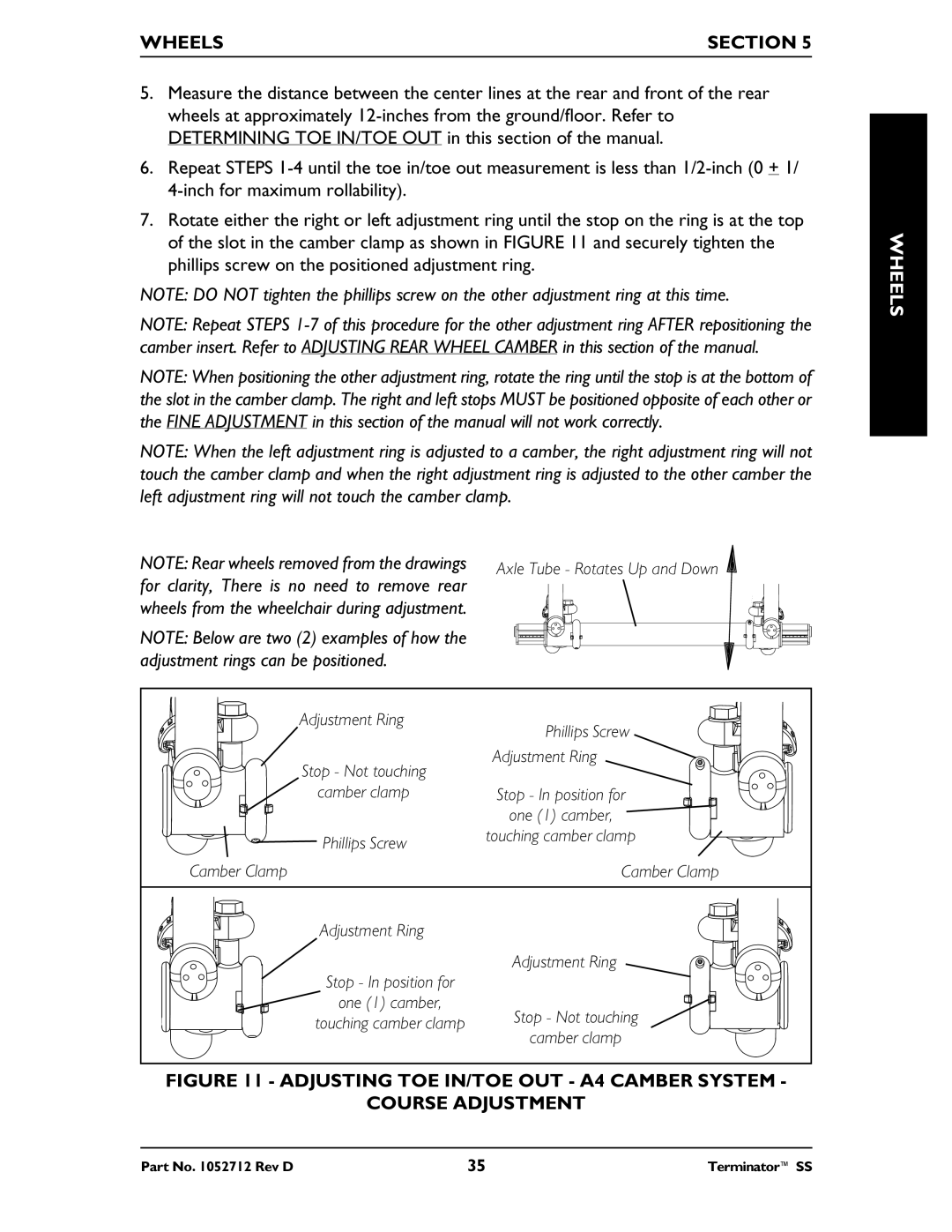
7.Rotate either the right or left adjustment ring until the stop on the ring is at the top of the slot in the camber clamp as shown in FIGURE 11 and securely tighten the phillips screw on the positioned adjustment ring.
NOTE: DO NOT tighten the phillips screw on the other adjustment ring at this time.
NOTE: Repeat STEPS
NOTE: When positioning the other adjustment ring, rotate the ring until the stop is at the bottom of the slot in the camber clamp. The right and left stops MUST be positioned opposite of each other or the FINE ADJUSTMENT in this section of the manual will not work correctly.
NOTE: When the left adjustment ring is adjusted to a camber, the right adjustment ring will not touch the camber clamp and when the right adjustment ring is adjusted to the other camber the left adjustment ring will not touch the camber clamp.
NOTE: Rear wheels removed from the drawings | Axle Tube - Rotates Up and Down | |
for clarity, There is no need to remove rear | ||
| ||
wheels from the wheelchair during adjustment. |
|
NOTE: Below are two (2) examples of how the adjustment rings can be positioned.
Adjustment Ring | Phillips Screw | |
| ||
Stop - Not touching | Adjustment Ring | |
| ||
camber clamp | Stop - In position for | |
| one (1) camber, | |
Phillips Screw | touching camber clamp | |
| ||
Camber Clamp | Camber Clamp | |
Adjustment Ring |
| |
Stop - In position for | Adjustment Ring | |
| ||
one (1) camber, | Stop - Not touching | |
touching camber clamp | ||
camber clamp | ||
|
FIGURE 11 - ADJUSTING TOE IN/TOE OUT - A4 CAMBER SYSTEM -
COURSE ADJUSTMENT
WHEELS
Part No. 1052712 Rev D | 35 | Terminator™ SS |