WHEELS | SECTION 5 |
|
|
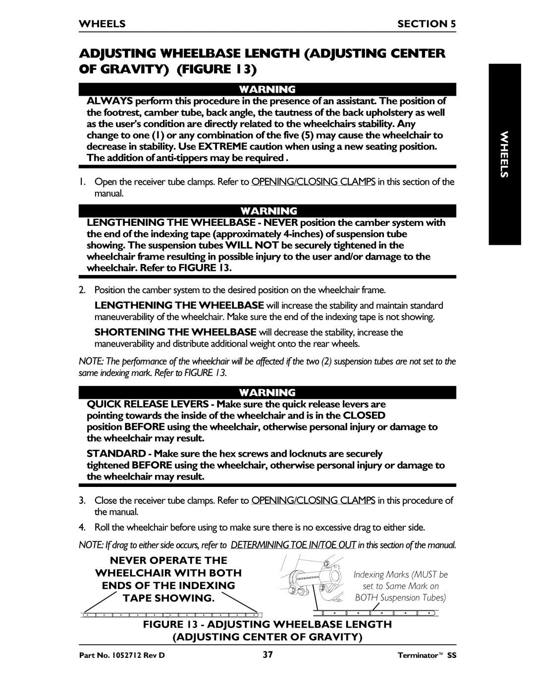
ADJUSTING WHEELBASE LENGTH (ADJUSTING CENTER OF GRAVITY) (FIGURE 13)
WARNING
ALWAYS perform this procedure in the presence of an assistant. The position of the footrest, camber tube, back angle, the tautness of the back upholstery as well as the user's condition are directly related to the wheelchairs stability. Any change to one (1) or any combination of the five (5) may cause the wheelchair to decrease in stability. Use EXTREME caution when using a new seating position. The addition of
1.Open the receiver tube clamps. Refer to OPENING/CLOSING CLAMPS in this section of the manual.
WARNING
LENGTHENING THE WHEELBASE - NEVER position the camber system with the end of the indexing tape (approximately
2.Position the camber system to the desired position on the wheelchair frame.
LENGTHENING THE WHEELBASE will increase the stability and maintain standard maneuverability of the wheelchair. Make sure the end of the indexing tape is not showing.
SHORTENING THE WHEELBASE will decrease the stability, increase the maneuverability and distribute additional weight onto the rear wheels.
NOTE: The performance of the wheelchair will be affected if the two (2) suspension tubes are not set to the same indexing mark. Refer to FIGURE 13.
WARNING
QUICK RELEASE LEVERS - Make sure the quick release levers are pointing towards the inside of the wheelchair and is in the CLOSED
position BEFORE using the wheelchair, otherwise personal injury or damage to the wheelchair may result.
STANDARD - Make sure the hex screws and locknuts are securely
tightened BEFORE using the wheelchair, otherwise personal injury or damage to the wheelchair may result.
3.Close the receiver tube clamps. Refer to OPENING/CLOSING CLAMPS in this procedure of the manual.
4.Roll the wheelchair before using to make sure there is no excessive drag to either side.
NOTE: If drag to either side occurs, refer to DETERMINING TOE IN/TOE OUT in this section of the manual.
NEVER OPERATE THE |
|
WHEELCHAIR WITH BOTH | Indexing Marks (MUST be |
ENDS OF THE INDEXING | set to Same Mark on |
TAPE SHOWING. | BOTH Suspension Tubes) |
FIGURE 13 - ADJUSTING WHEELBASE LENGTH |
(ADJUSTING CENTER OF GRAVITY) |
WHEELS
Part No. 1052712 Rev D | 37 | Terminator™ SS |
