WHEELS
SECTION 5 | WHEELS |
|
|
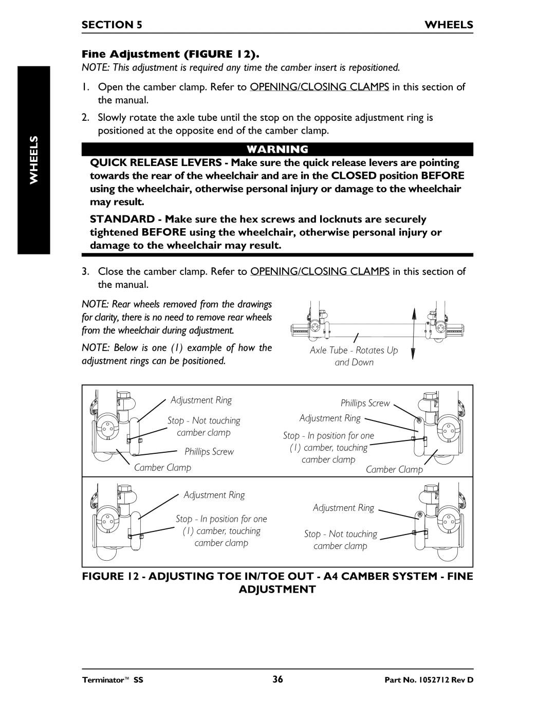
Fine Adjustment (FIGURE 12).
NOTE: This adjustment is required any time the camber insert is repositioned.
1.Open the camber clamp. Refer to OPENING/CLOSING CLAMPS in this section of the manual.
2.Slowly rotate the axle tube until the stop on the opposite adjustment ring is positioned at the opposite end of the camber clamp.
WARNING
QUICK RELEASE LEVERS - Make sure the quick release levers are pointing towards the rear of the wheelchair and are in the CLOSED position BEFORE using the wheelchair, otherwise personal injury or damage to the wheelchair may result.
STANDARD - Make sure the hex screws and locknuts are securely tightened BEFORE using the wheelchair, otherwise personal injury or damage to the wheelchair may result.
3.Close the camber clamp. Refer to OPENING/CLOSING CLAMPS in this section of the manual.
NOTE: Rear wheels removed from the drawings for clarity, there is no need to remove rear wheels from the wheelchair during adjustment.
NOTE: Below is one (1) example of how the adjustment rings can be positioned.
Axle Tube - Rotates Up
and Down
Adjustment Ring | Phillips Screw | |
| ||
Stop - Not touching | Adjustment Ring | |
camber clamp | Stop - In position for one | |
Phillips Screw | (1) camber, touching | |
camber clamp | ||
Camber Clamp | ||
Camber Clamp | ||
Adjustment Ring |
| |
Stop - In position for one | Adjustment Ring | |
| ||
(1) camber, touching | Stop - Not touching | |
camber clamp | ||
camber clamp | ||
|
FIGURE 12 - ADJUSTING TOE IN/TOE OUT - A4 CAMBER SYSTEM - FINE
ADJUSTMENT
Terminator™ SS | 36 | Part No. 1052712 Rev D |
