WHEELS
SECTION 5 | WHEELS |
|
|
10.Reposition the camber inserts to the highest degree of camber. Refer to ADJUSTING REAR WHEEL CAMBER in this section of the manual.
11.Repeat STEP 3.
12.Close the LEFT camber clamp. Refer to OPENING/CLOSING CLAMPS in this section of the manual.
13.Rotate the RIGHT toe adjustment ring until the tab stops against the UPPER metal tab on the camber clamp.
14.Securely tighten set screw on RIGHT toe adjustment ring.
15.Repeat STEP 7.
16.Perform one (1) of the following:
A.TOE IN/TOE OUT MEASUREMENT IS WITHIN ±1/8-INCH -
i.Proceed to STEP 17.
B.TOE IN/TOE OUT MEASUREMENT IS NOT WITHIN ±1/8-INCH -
i.Repeat STEP 1.
ii.Loosen the set screw on the right toe adjustment ring.
iii.Repeat STEP 3.
iv.Repeat STEPS
17.If desired, reposition camber inserts to the desired degree of camber. Refer to ADJUSTING REAR WHEEL CAMBER in this section of the manual.
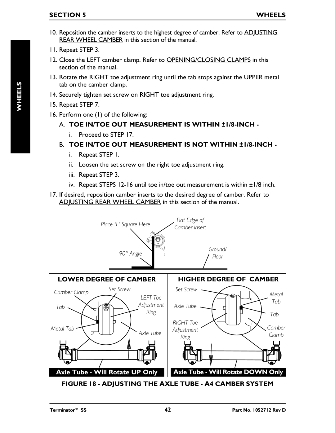
Place "L" Square Here
90° Angle
Flat Edge of
Camber Insert
Ground/
Floor
LOWER DEGREE OF CAMBER | HIGHER DEGREE OF CAMBER | |||
Camber Clamp | Set Screw | Set Screw | Metal | |
LEFT Toe |
| |||
|
| |||
|
| Tab | ||
Tab | Adjustment | Axle Tube | ||
| ||||
| Ring |
| Tab | |
|
|
| ||
Metal Tab |
| RIGHT Toe | Camber | |
Axle Tube | Adjustment | |||
| Ring | Clamp | ||
|
|
| ||
Axle Tube - Will Rotate UP Only | Axle Tube - Will Rotate DOWN Only |
FIGURE 18 - ADJUSTING THE AXLE TUBE - A4 CAMBER SYSTEM
Terminator™ SS | 42 | Part No. 1052712 Rev D |