FOOTREST
PROCEDURE 7 | FOOTREST |
|
|
ADJUSTING FOOTREST
Position.
1.Loosen the hex screws on the mounting bracket.
2.Slide the footrest assembly along the frame to the desired position.
3.Tighten the hex screws on the mounting bracket.
Height.
1.Loosen the set screw securing the upper and lower footrest support tubes.
2.Reposition the footrest up or down as desired.
3.Tighten the set screw to secure the upper and lower footrest support tubes.
Angle.
1.Loosen the locknuts securing the footplate mounting bracket.
2.Adjust the angle of the footplate as desired.
3.Tighten the locknuts securing the footplate mounting bracket.
Depth.
1.Remove the locknuts and button screws securing the footplate mounting bracket.
2.Reposition the footplate to the desired set of mounting holes.
3.Install the button screws through the footplate, footstrap and footplate mounting bracket.
4.Secure the button screws with the locknuts. Tighten securely.
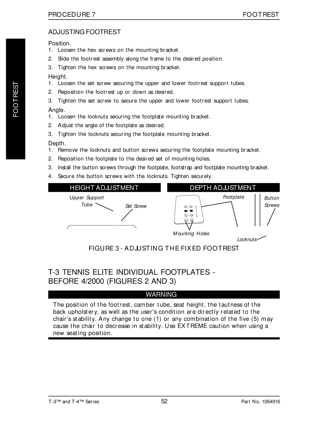
HEIGHT ADJUSTMENT
Upper Support |
|
Tube | Set Screw |
DEPTH ADJUSTMENT
Footplate Button
Screws
Mounting Holes
Locknuts ![]()
FIGURE 3 - ADJUSTING THE FIXED FOOTREST
T-3 TENNIS ELITE INDIVIDUAL FOOTPLATES - BEFORE 4/2000 (FIGURES 2 AND 3)
WARNING
The position of the footrest, camber tube, seat height, the tautness of the back upholstery, as well as the user's condition are directly related to the chair's stability. Any change to one (1) or any combination of the five (5) may cause the chair to decrease in stability. Use EXTREME caution when using a new seating position.
52 | Part No. 1054916 |