WHEELS | PROCEDURE 6 |
|
|
WARNING
Make sure the detent pin and locking pins of the
The locking pins MUST be protruding past the inside of the rear wheel axle bushing for a positive lock.
Keep locking pins clean.
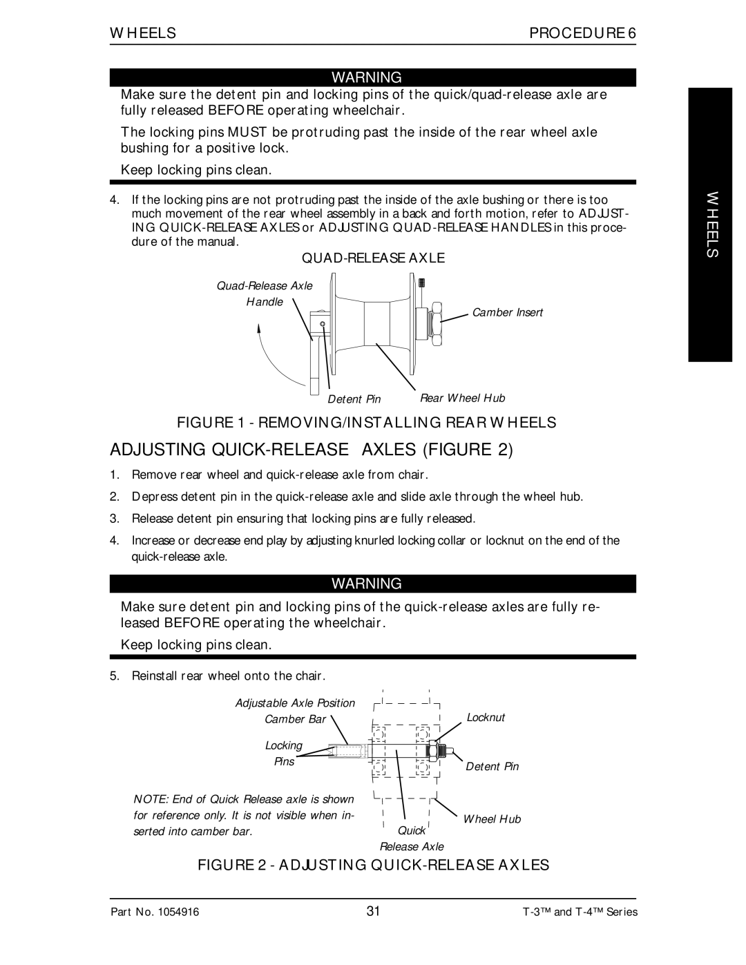
4.If the locking pins are not protruding past the inside of the axle bushing or there is too much movement of the rear wheel assembly in a back and forth motion, refer to ADJUST- ING
Handle
Camber Insert
Detent Pin | Rear Wheel Hub |
FIGURE 1 - REMOVING/INSTALLING REAR WHEELS
ADJUSTING QUICK-RELEASE AXLES (FIGURE 2)
1.Remove rear wheel and
2.Depress detent pin in the
3.Release detent pin ensuring that locking pins are fully released.
4.Increase or decrease end play by adjusting knurled locking collar or locknut on the end of the
WARNING
Make sure detent pin and locking pins of the
Keep locking pins clean.
WHEELS
5. Reinstall rear wheel onto the chair.
Adjustable Axle Position
Camber Bar
Locking
Pins
NOTE: End of Quick Release axle is shown for reference only. It is not visible when in- serted into camber bar.
Quick
Locknut
Detent Pin
Wheel Hub
Release Axle
FIGURE 2 - ADJUSTING QUICK-RELEASE AXLES
Part No. 1054916 | 31 |