OPTIONAL | PROCEDURE 8 |
|
|
INSTALLING/ADJUSTING REMOVABLE ANTI-TIPPER
T-3 ADJUSTABLE - AFTER 2001 (FIGURE 2)
WARNING
If the rear wheel size, rear wheel camber or the position of the adjustable axle camber bar is changed, the rear swivel caster MUST be readjusted to maintain a 1/4 to
OPTIONAL
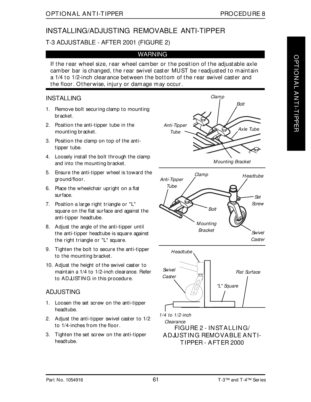
INSTALLING
1.Remove bolt securing clamp to mounting bracket.
2.Position the
3.Position the clamp on top of the anti- tipper tube.
4.Loosely install the bolt through the clamp and into the mounting bracket.
5.Ensure the
6.Place the wheelchair upright on a flat surface.
7.Position a large right triangle or "L" square on the flat surface and against the
8.Adjust the angle of the
9.Tighten the bolt to secure the
Clamp
| Bolt | |
Axle Tube | ||
Tube | ||
|
| Mounting Bracket |
Clamp | Headtube |
|
Tube
| Set |
Bolt | Screw |
| |
Mounting |
|
Bracket | Swivel |
| |
| Caster |
Headtube |
|
ANTI-TIPPER
10.Adjust the height of the swivel caster to maintain a 1/4 to
ADJUSTING
1.Loosen the set screw on the
2.Adjust the
3.Tighten the set screw on the
Swivel | Flat Surface | |
Caster | ||
| ||
| "L" Square |
1/4 to
Clearance
FIGURE 2 - INSTALLING/
ADJUSTING REMOVABLE ANTI-
TIPPER - AFTER 2000
Part No. 1054916 | 61 |