WHEELS
PROCEDURE 6 | WHEELS |
|
|
WARNING
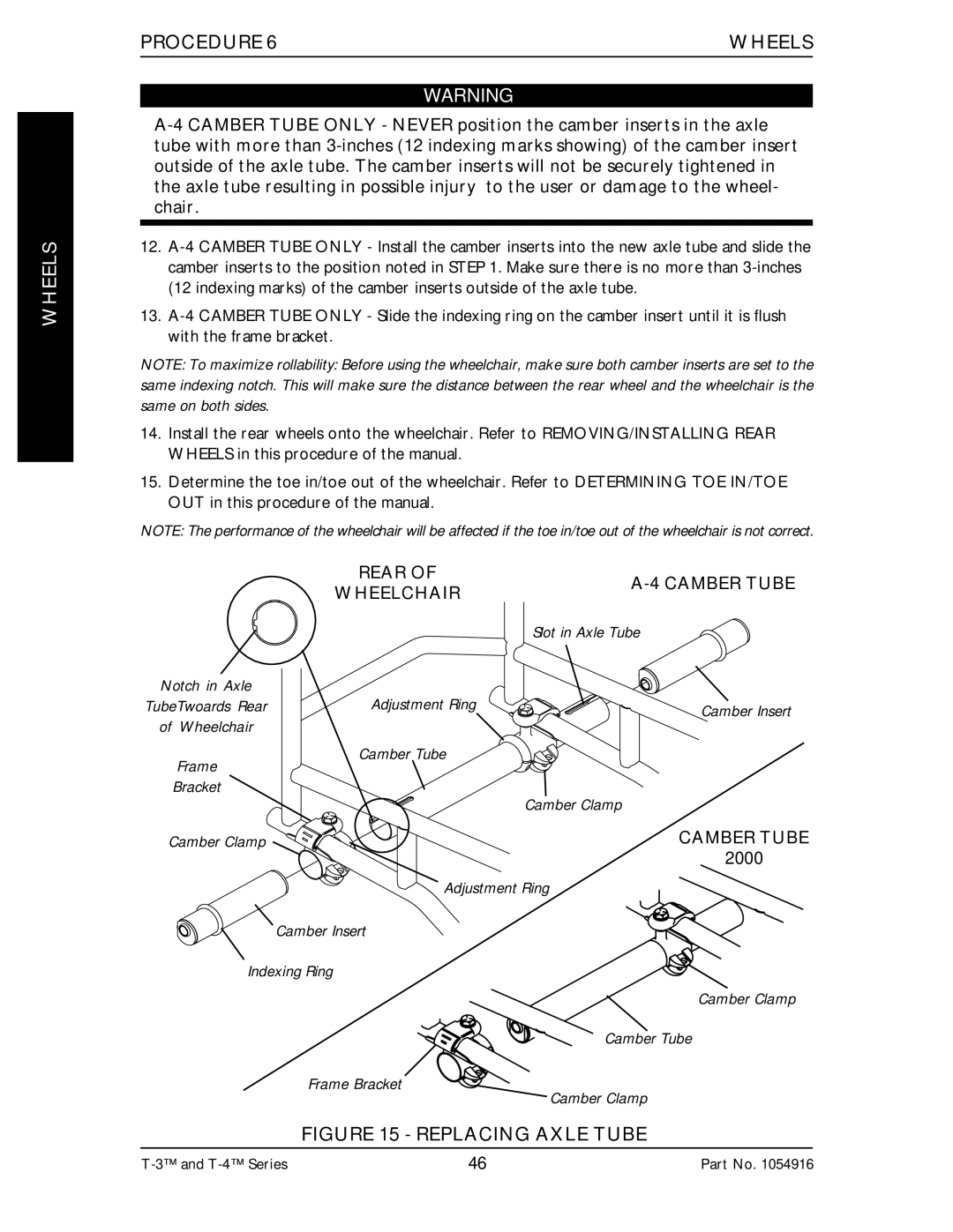
12.
13.
NOTE: To maximize rollability: Before using the wheelchair, make sure both camber inserts are set to the same indexing notch. This will make sure the distance between the rear wheel and the wheelchair is the same on both sides.
14.Install the rear wheels onto the wheelchair. Refer to REMOVING/INSTALLING REAR WHEELS in this procedure of the manual.
15.Determine the toe in/toe out of the wheelchair. Refer to DETERMINING TOE IN/TOE OUT in this procedure of the manual.
NOTE: The performance of the wheelchair will be affected if the toe in/toe out of the wheelchair is not correct.
REAR OF | ||
WHEELCHAIR | ||
| ||
| Slot in Axle Tube |
Notch in Axle
TubeTwoards RearAdjustment Ring![]() Camber Insert
Camber Insert
of Wheelchair
Frame | Camber Tube |
| |
Bracket | Camber Clamp |
| |
Camber Clamp | CAMBER TUBE |
| 2000 |
| Adjustment Ring |
Camber Insert
Indexing Ring
Frame Bracket
Camber Clamp
Camber Tube
Camber Clamp
FIGURE 15 - REPLACING AXLE TUBE
46 | Part No. 1054916 |