FOOTREST | PROCEDURE 7 |
|
|
CHANGING FOOTPLATE ANGLE
1.Loosen, but do not remove the button screws and locknuts that secure the footplates to the footplate system mounting bracket.
2.Adjust the footplate to the desired angle for the user.
3.Tighten the button screws and locknuts that secure the footplates to the footplate system mounting bracket securely.
4.Repeat STEPS
CHANGING FOOTPLATE DEPTH
Repositioning Footplate.
1.Remove the button screws and locknuts that secure the footplate and footplate clamp to the footplate system mounting clamp.
2.Adjust the footrest to the desired depth for the user.
3.Line up the mounting holes in the footplate and footplate clamp.
4.Reinstall the button screws and locknuts that secure the footplate and footplate clamp to the footplate system mounting clamp and tighten securely.
5.Repeat STEPS
Repositioning Footplate Mounting Bracket.
1.Remove the button screws and locknuts that secure the footplate mounting bracket to the chair frame.
FOOTREST
2.Move the footplate mounting bracket to the desired position for the user.
3.Reinstall the button screws and locknuts that secure the footplate mounting bracket to the chair frame and tighten securely.
CHANGING FOOTPLATE HEIGHT
1.Remove the button screws and locknuts that secure the fooplate system mount- ing clamp to the footplate mounting bracket.
2.Position the footplate system mounting clamp on the footplate mounting bracket at the desired height for the user.
3.Reinstall the button screws and locknuts that secure the fooplate system mount- ing clamp to the footplate mounting bracket and tighten securely.
4.Repeat STEPS
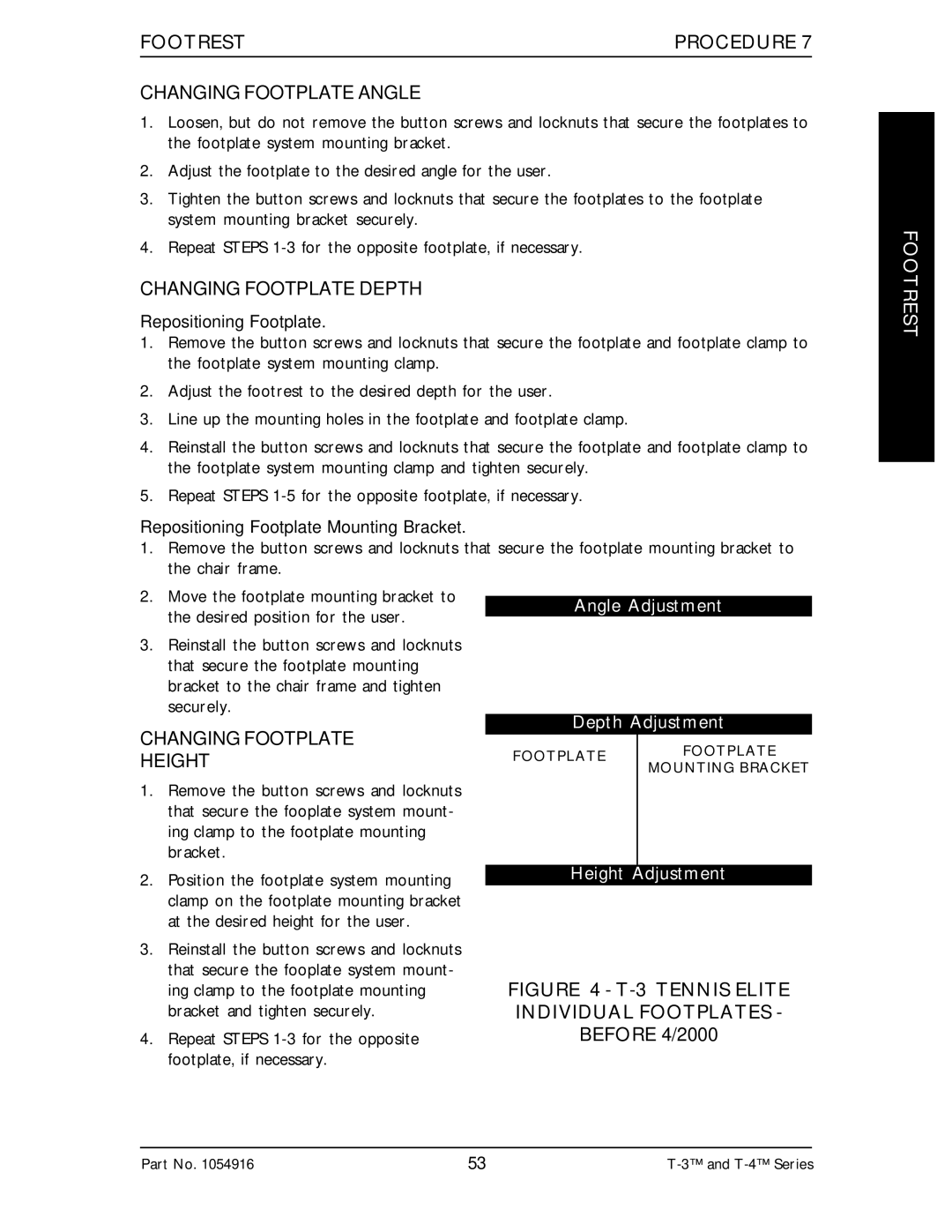
Angle Adjustment
Depth Adjustment
FOOTPLATE | FOOTPLATE | |
MOUNTING BRACKET | ||
|
Height Adjustment
FIGURE 4 - T-3 TENNIS ELITE INDIVIDUAL FOOTPLATES - BEFORE 4/2000
Part No. 1054916 | 53 |
