WHEELS
PROCEDURE 6 | WHEELS |
|
|
HANDRIM REPLACEMENT (FIGURE 5)
1.Remove the rear wheel from the chair, refer to REMOVING/INSTALLING THE REAR WHEELS in this procedure of the manual.
WARNING
Tire MUST be deflated before any disassembly procedures are performed.
2.Remove all air from the tube by pressing down on the pin in the center of the valve stem.
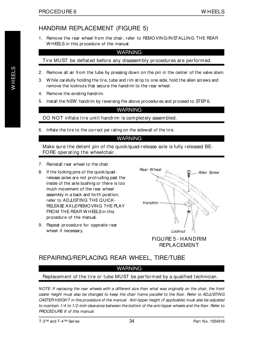
3.While carefully holding the tire, tube and rim strip to one side, hold the allen screws and remove the locknuts that secure the handrim to the rear wheel.
4.Remove the existing handrim.
5.Install the NEW handrim by reversing the above procedures and proceed to STEP 6.
WARNING
DO NOT inflate tire until handrim is completely assembled.
6. Inflate the tire to the correct psi rating on the sidewall of the tire.
WARNING
Make sure the detent pin of the
7.Reinstall rear wheel to the chair.
8.If the locking pins of the quick/quad- release axles are not protruding past the inside of the axle bushing or there is too much movement of the rear wheel assembly in a back and forth position, refer to ADJUSTING THE QUICK-
RELEASE AXLE/REMOVING THE PLAY FROM THE REAR WHEELS in this procedure of the manual.
9.Repeat procedure for opposite rear wheel if necessary.
Rear Wheel | Allen Screw |
|
Handrim
Locknut
FIGURE 5 - HANDRIM
REPLACEMENT
REPAIRING/REPLACING REAR WHEEL, TIRE/TUBE
WARNING
Replacement of the tire or tube MUST be performed by a qualified technician.
NOTE: If replacing the rear wheels with a different size than what was originally on the chair, the front caster height must also be changed to keep the chair frame parallel to the floor. Refer to ADJUSTING CASTER HEIGHT in this procedure of the manual.
34 | Part No. 1054916 |