PROCEDURE 3 | BACK | |
|
|
|
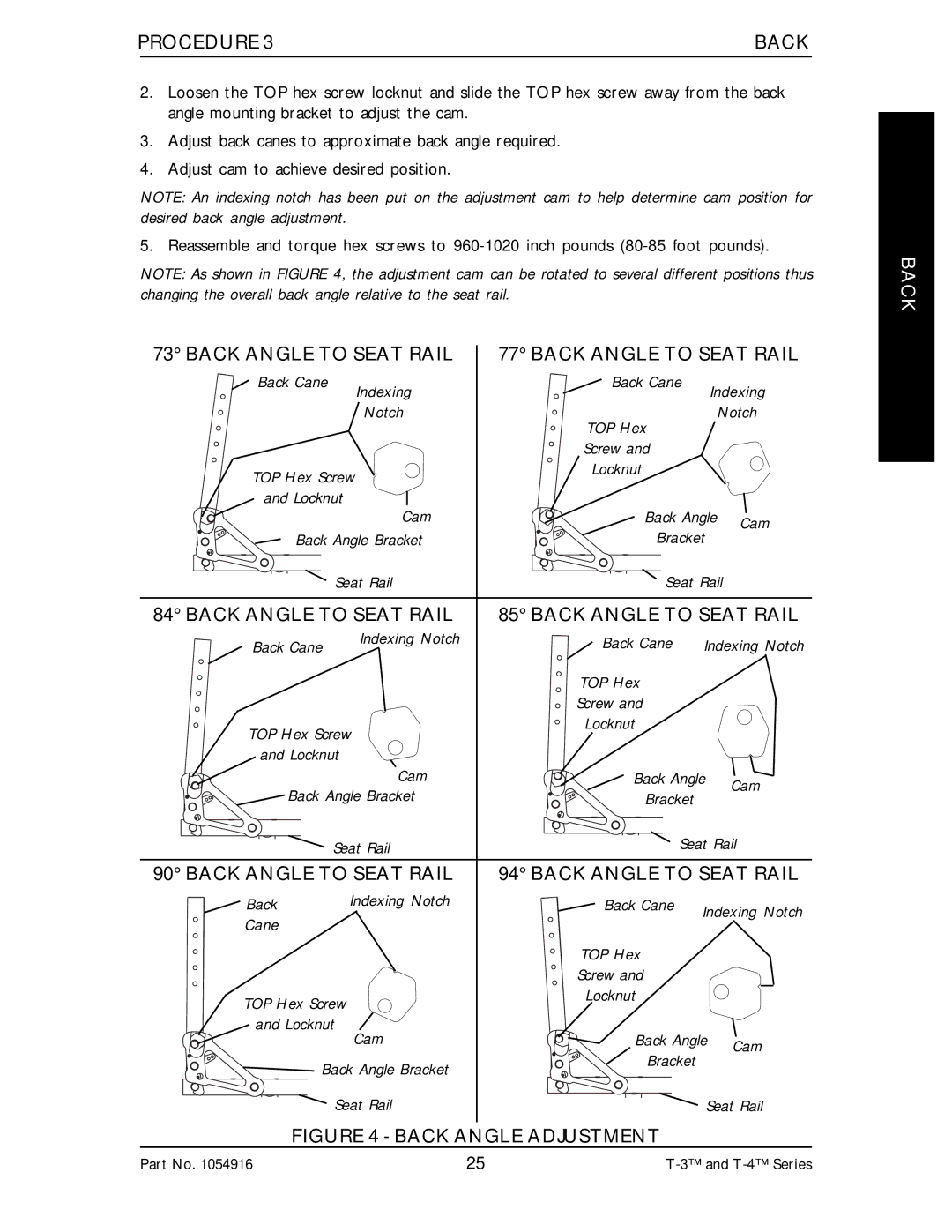
2.Loosen the TOP hex screw locknut and slide the TOP hex screw away from the back angle mounting bracket to adjust the cam.
3.Adjust back canes to approximate back angle required.
4.Adjust cam to achieve desired position.
NOTE: An indexing notch has been put on the adjustment cam to help determine cam position for desired back angle adjustment.
5. Reassemble and torque hex screws to
NOTE: As shown in FIGURE 4, the adjustment cam can be rotated to several different positions thus changing the overall back angle relative to the seat rail.
73° BACK ANGLE TO SEAT RAIL | 77° BACK ANGLE TO SEAT RAIL | ||||
Back Cane | Indexing | Back Cane |
| Indexing | |
|
|
| |||
| Notch | TOP Hex |
| Notch | |
|
|
|
|
| |
|
| Screw and |
|
|
|
TOP Hex Screw | Locknut |
|
|
| |
|
|
|
| ||
and Locknut | Cam | Back Angle |
| ||
| Cam | ||||
Back Angle Bracket | Bracket |
| |||
|
| ||||
Seat Rail | Seat Rail |
| |||
84° BACK ANGLE TO SEAT RAIL | 85° BACK ANGLE TO SEAT RAIL | ||||
Back Cane | Indexing Notch | Back Cane Indexing Notch | |||
|
| TOP Hex |
|
|
|
|
| Screw and |
|
|
|
TOP Hex Screw | Locknut |
|
|
| |
|
|
|
| ||
and Locknut |
|
|
|
|
|
| Cam | Back Angle |
| Cam | |
Back Angle Bracket | Bracket |
|
| ||
|
|
| |||
Seat Rail | Seat Rail | ||||
90° BACK ANGLE TO SEAT RAIL | 94° BACK ANGLE TO SEAT RAIL | ||||
Back | Indexing Notch | Back Cane | Indexing Notch | ||
Cane |
|
| |||
|
|
|
|
| |
|
| TOP Hex |
|
|
|
|
| Screw and |
|
|
|
TOP Hex Screw |
| Locknut |
|
|
|
|
|
|
|
| |
and Locknut | Cam | Back Angle |
| ||
| Cam | ||||
|
| Bracket |
|
| |
Back Angle Bracket |
|
|
| ||
|
|
|
| ||
Seat Rail |
|
| Seat Rail | ||
FIGURE 4 - BACK ANGLE ADJUSTMENT
BACK
Part No. 1054916 | 25 |